Research log: Lighthouse positioning
← Back to Kevin's homepagePublished: 2019 Dec 17Last updated: 2019 Dec 22I’d like to precisely localize (< 1mm) a robot within a roughly 3m square area.
At first I considered a cheap webcam approach — visual odometry or even just reading linear fiducials (tape measures) with OpenCV — but a friend suggested Valve’s “Lighthouse” positioning system, which looks much more promising. (Also: A great excuse to goof with microcontrollers and analog circuitry.)
These are my research notes. They’re written for my own reference, but feel free to email me if you’re working on a similar project.
Lighthouse tl;dr
The lighthouse system is based on precise timing of near-infrared light pulses. A base station (“lighthouse”) emits a wide field of view sync pulse and then sweeps either a horizontal or vertical beam. A receiver uses the duration between the sync and sweep pulses to determine its horizontal/vertical angular position with respect to the lighthouse. Here’s a great animation:
Receivers do not need to communicate with the lighthouse, which is just always broadcasting.
The original (1.0) base station can be purchased on Amazon for $130 and a revised (2.0) base station can be purchased from Valve for $149 (or as part of the Vive Pro System for $1,400, if you actually want to play videogames).
The 2.0 base stations have a curved front plate and emit a fancier modulated signal of some kind. Apparently they’re mechanically simpler and allow for combining more lighthouses to create a larger tracked area. See libsurvive for discussion and reverse engineering attempts.
For my project, I’m using the 1.0 base station since there’s more available prior art and the signal looks simpler to decode.
Lighthouse resources
Many people have worked on building open source lighthouse receivers and Alan Yates (the original designer) actively helps on Reddit as /u/vk2zay. Resources that I’ve found most helpful:
Light Emissions: pulse timing information and binary structure of the OOTX frame that base stations use to broadcast factory calibration parameters (measured offsets from their ideal behavior) and the base station’s gravitational field reading.
Zippies: adorable robots with open source lighthouse receiver circuit and code for Atmel SAMD21 (ARM32) architecture. When I was first investigating the lighthouse, the Zippies creator confirmed that he is getting sub-mm accuracy, inspired me to pursue my own development.
Trammel Hudson’s 2016 investigation: Several types of receivers (sensor module, phototransistor, photodiode + transimpedence amplifier) and discussion of math for localization.
First attempt
Triad Semiconductor sells chips for the Valve Lighthouse system:
TS4112: “Complete Light-to-Digital Sensor with Integrated Photodiode” isn’t yet available (“join our waitlist”)
TS4231: “2nd Generation Light to Digital Converter (Envelope and Data)” I think maybe only works with Lighthouse 2.0 (it mentions modulated signals) and is packaged as 9 ball pins in a 1.3 mm square, so no way I can solder that by hand.
However, I decided to start by building a Zippies receiver circuit since the PCB was easy to order via OSHPark and the designer was responsive and helpful. They suggested I use a BPW34 photodiode rather than the specified BP104, but otherwise I assembled circuit as drawn:
I powered it at 3.3V via an STM32 black pill which itself was powered from my laptop’s USB 5V rail via an ST-Link V2 programmer and set it about 20cm away from a lighthouse set to mode A.
Miraculously (considering this was my first time soldering 0603 components by hand), the expected signals appeared on the oscilloscope:
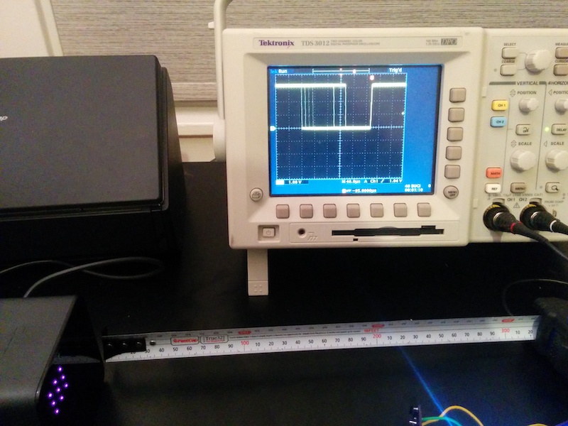
Note the four different sync pulse lengths (encoding two bits; a data bit of the OOTX frame and a bit indicating whether horizontal or vertical pulse is about to sweep) and the two shorter sync pulses.
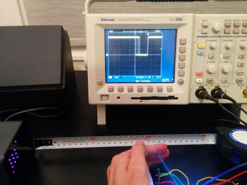
However, when I began to try and decode the OOTX packet I realized that the sync pulses were too long. Putting my hand in front of the receiver blocks the sweep pulses but not the sync pulses (the former being focused laser sweeps and the latter broad-illumination that presumably reflects off my walls and makes it to the receiver).
Curiously, blocking the sweep pulses reduces the duration of the sync pulses:
My oscilloscope probes were too big to measure anything besides the board’s output signal, but for fun, I also took a single-capture trace of a lone photodiode (off-board, blue), triggered by the receiver’s output (yellow):
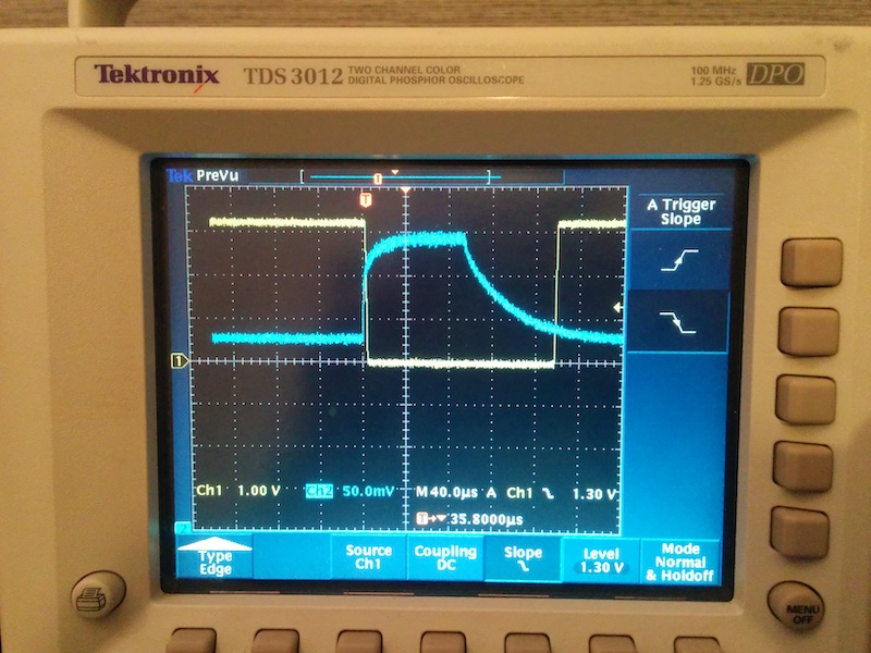
This signal suggests to me that there’s about 80μs of lag between the end of the laser pulse and the digital signal switching.
So there’s some problem in my receiver circuit. (It can’t be the lighthouse, which isn’t going to change its timing based on the location of my hand.)
Unfortunately, everything I learned about analog electronics came from a one semester undergraduate lab a decade ago. After staring at the Zippies receiver schematic for a while, it became clear that I’d forgotten most of it.
Analog electronics review
Here’s what I’ve found most helpful over the past week:
Scherz and Monk’s Practical Electronics for Inventors overviews theory, practical considerations, and has a ton of worked example circuits in lots of applications; probably the single most useful book to have.
Photodiode/Transimpedance Amplifier Design, a well-presented 10 minute video explaining a circuit designed for a similar application (reading digital signals via photodiode); starts from a basic transimpedence amplifier circuit and explains various additions for to remove DC offset and improve the signal read out.
Johnson’s Photodetection and Measurement: Maximizing Performance in Optical Systems assumes some electrical knowledge (I couldn’t make much sense until after reviewing the theory chapters of Scherz and Monk) and is clearly written by an experienced practitioner. Lots of specific advice for improving photodetection performance (both electrically and optically), as well as prototyping tricks for the lab.
Graeme’s Photodiode Amplifiers: OP AMP Solutions: Recommended by the YouTuber, but I found it pretty dry and couldn’t get past the first chapter; seems to be written for solid-state physicists.
Hobbs’s Building Electro-Optical Systems: Making It all Work: Practical and seems fairly readable, though it’s focused more on instrumentation (sensitivity and noise calculations) that doesn’t immediately apply to my digital signal needs.
Okay, here’s the part where I throw down a bunch of scattered notes and questions for my own reference. (Though please let me know if any of my reasoning is incorrect here!)
Decibels
A Bel (named after Alexander with the telephones) is a power ratio:
$$ 1\,\mathrm{Bel} = \log\left( \frac{\mbox{Output power}}{\mbox{Input power}} \right). $$
A decibel has a factor of ten thrown in:
$$ 1\,\mathrm{dB} = 10 \log\left( \frac{\mbox{Output power}}{\mbox{Input power}} \right). $$
but if you’re talking about frequency, current, or voltage, it’s a factor of 20 because the power is proportional to the amplitude squared (and the square pops out of the logarithm).
People like to talk about halving/doubling: $10\log(\frac{\mathrm{power}}{2}) = 20\log(\frac{\mathrm{amplitude}}{\sqrt{2}}) \approx -3\,\mathrm{dB}$.
The cutoff frequency $f_c$ of a filter is where the signal is reduced (“attenuated”) by a factor of -3dB; which corresponds to a current reduction of $1 / \sqrt 2 \approx 0.71$.
Impedances + passive filters
The complex impedance of a capacitor is:
$$ Z_c = \frac{1}{j \omega C} = \frac{-j}{2\pi f C} $$
The angular frequency is related to the, uh, measurable one by $\omega = 2\pi f$.
A passive filter works just like a voltage divider, except the response is frequency dependent. A high pass and low pass filter are very similar: An input signal flowing into a series resistor and capacitor down to ground.
If the signal flows through the resistor first and you measure across the capacitor, you mostly “see” the low frequency signal (since the cap will have a high impedance for them; alternatively, the high frequency signals will short through). If the signal flows through the cap first and you measure over the resistor, high frequency signals will dominate.
The signal will be attenuated by half when the impedances of the resistor and capacitor are equal, which is at the cutoff frequency:
$$ f_c = \frac{1}{2\pi R C}. $$
Why isn’t this circuit working, again?
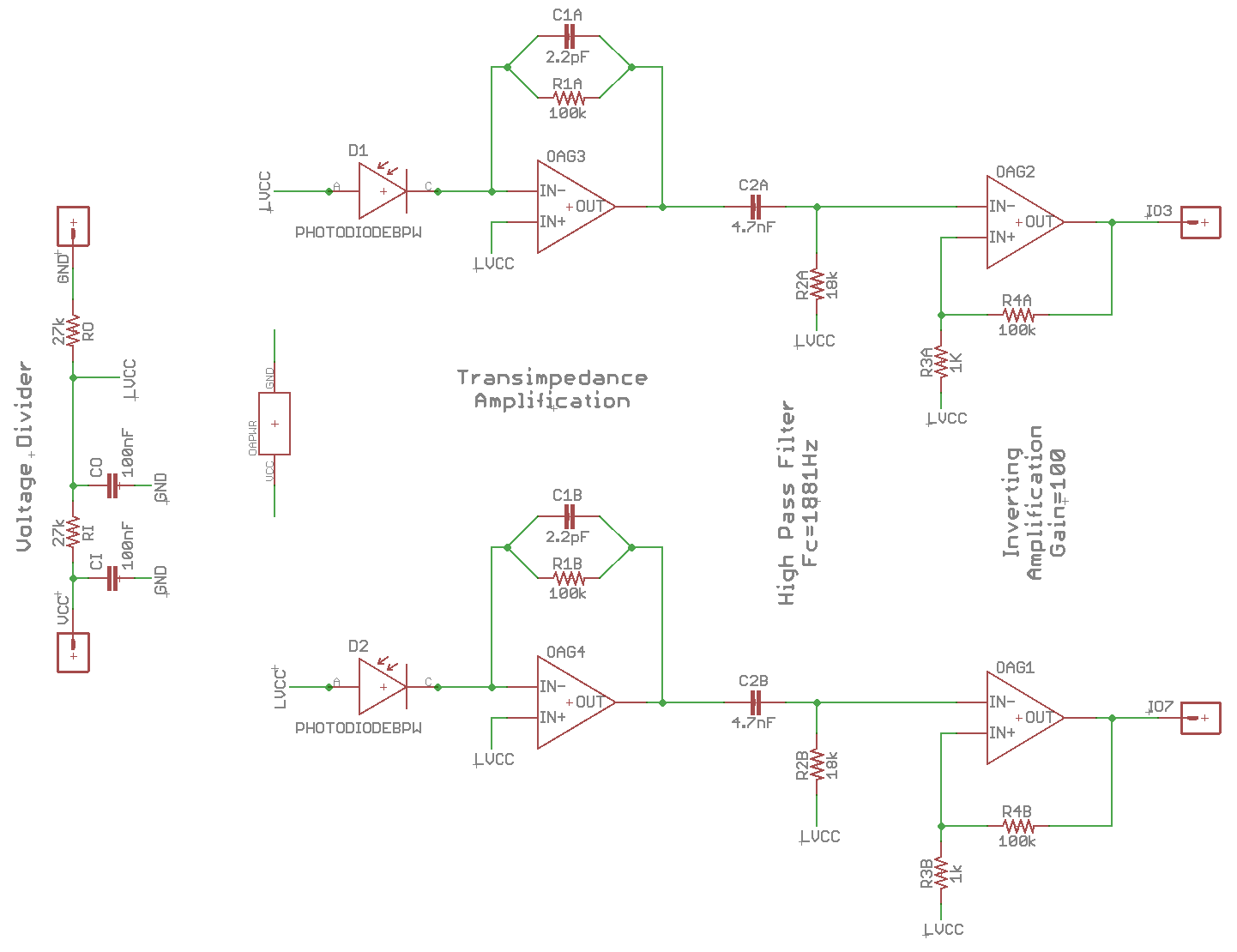
Both Hudson’s and the Zippies circuit are based on a design tweeted by Yates consisting of a transimpedence amplifier, high-pass filter, and comparator. (Yates: “note that this circuit is slow and insensitive, but it is also very cheap, easy to make and useful as a basis for better things.”)
I have a lot of questions, which I’ve sketched out below.
Here’s the Zippies circuit again for reference:
My initial notes:
Photodiode current flows “backwards” (cathode to anode) when light strikes.
tlv2464 op amp specs (rounded to the, uh, bad directions):
- differential input voltage: -0.2 V to Vdd + 0.2 V
- input bias current: 14 nA
- output current: ±40 mA
- unity gain slew rate: 0.8 V/μs
- gain bandwidth product: 5.2 MHz
bpw34 photodiode specs:
- max reverse bias voltage: 16 V
- spectral sensitivity at 870nm: 0.65 A/W
- capacitance @ 1MHz with no bias voltage: 72 pF
- typical photocurrent for 1 mW/cm² of 870nm light and 5V reverse bias: 50 μA
This summary graphic from Johnson’s book is also very helpful:
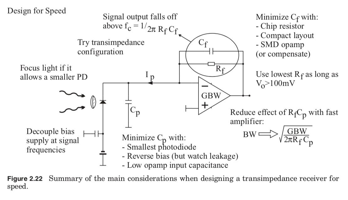
How fast do we need to go, anyway?
This first Google result rule of thumb suggests that the necessary bandwidth can be derived as 0.35 / (10% to 90% rise time). From my scope trace of the bare photodiode, that time looks like, what, maybe 20μs, so this rule of thumb suggests we need a bandwidth around 20 kHz.
Johnson’s summary graphic suggests that our transimpedence amplifier has a bandwidth of roughly
$$ \sqrt{\frac{\mbox{GBW}}{2 \pi R C_p}} = \sqrt{\frac{5.2\,\mbox{MHz}}{2 \pi \cdot 100\,\mathrm{k\Omega} \cdot 72\,\mathrm{pF}}} \approx 339\,\mathrm{kHz}, $$
which is an order of magnitude more than we need. Arguably even more, since (I think) the in-circuit photodiode rise time will be reduced by the amp’s virtual ground (which negates the slowdown due to photodiode’s parasitic capacitance). TODO: solder wires across in-circuit diode and compare signal to transimpedance output to verify that the latter accurately tracks the signal speed of the former.
Can the transimpedence amp keep up with photodiode current?
Probably.
The back of the lighthouse says “Class 1 laser product” and this Laser Safety Facts.com chart starts with Class 2 at 0–1mW. So say there’s 1mW of laser and 100% of the power magically arrives at the photodiode.
Diode specs say this will yield 50μA of current (at 5V reverse bias — not sure if there’s any current difference in my unbiased case), but the amp can output about 1000x more current than this, so I think it should be able to keep up.
TODO: measure photodiode output current somehow. Can my girlfriend’s dad’s 1998 oscilloscope integrate voltage drop over a resistor? Will I have to build an integrator with these op amps I have laying around? Can I just buy an electrical engineering undergrad a six pack to figure this out for me?
Why doesn’t the transimpedence amp compare the signal to ground?
In the typical inverting amplifier setup, signals go into the inverting terminal and the non-inverting terminal is grounded. What’s usually omitted is the op amp’s power rails, which are usually split (i.e., ±6 V rather than 12 V and 0 V).
That’s because op amps aren’t happy when their inputs go near or beyond their power rails.
Look at Johnson’s graphic: When light strikes the photodiode, current flows as shown and pulls the inverting input below ground until the amp can catch up with negative feedback current.
So even though the tlv2464 is described as “rail-to-rail input/output” and the lm358 amp in Yate’s drawing allows input voltages from 0 to V₊ - 1, my guess is that it’s simply better to not risk hitting the floor via overshoot and just centering the input signal within the available voltage. (Which is what both designs do, centering at LVCC = VCC / 2, provided by the voltage divider at left in Zippies schematic.)
What’s the high-pass filter about?
Based on the YouTube video design of a similar circuit, I suspect this filter was added to remove the DC offset from the amplified signal caused by ambient light. The cutoff frequency is:
$$ f_c = \frac{1}{2\pi R C} = \frac{1}{2\pi \cdot 18\,\mathrm{k\Omega} \cdot 4.7\,\mathrm{nF}} \approx 1.9\,\mathrm{kHz}, $$
which satisfyingly matches what was written on the Zippies schematic. This is well below the photodiode and transimpedence amplifier bandwidth, so there’s plenty of room for our interesting high frequency signals to pass through.
(TODO: presumably a too-high cutoff frequency would start to filter out the hundred-ish microseconds when the diode is illuminated by the sync pulse; how do I quantitatively think about this?)
Why is the final output signal inverted?
Short answer: photodiode signal is negative when light strikes, and that signal goes through two inverting inputs, so comes out negative on the other side. Long answer:
At a DC steady state
- all op amp terminals are balanced
- op amps aren’t emitting any current
- IO pin is at LVCC (because it’s tied there by R3 + R4)
When light strikes the photodiode:
- current flows “backwards” (cathode to anode), reducing the voltage at the op amp’s inverting terminal
- op amp then emits a positive voltage at its output terminal
- this raises the voltage at the second op amp’s inverting terminal
- the second op amp (which is configured with positive feedback) then clamps low
After the light stops, eventually:
- the feedback across the first op amp gets it to stop pushing current
- this lowers the voltage at the second op amp’s inverting terminal
- as soon as the voltage is lower than the non-inverting terminal, the second op amp starts pushing current
- the positive feedback loop latches back high
Why are we using an op amp with positive feedback?
The second op amp has positive feedback and thus acts as a comparator. My understanding is that this is not usually a very good idea because op-amps are designed for stability and linearity while comparators are designed for speed. A manufacturer says:
However, when an open-loop amplifier is used as a comparator, with its outputs swinging between their limits, its internal compensation capacitance—used to provide dynamic stability—causes the output to be slow to come out of saturation and slew through its output range.
I’m not sure what “slow” means here, but I’d be surprised if it were so slow to account for the 60+ μs sync pulse duration.
In our circuit we’re not using the op amp open-loop; we’re using it with positive feedback, which adds hysteresis and probably makes things even slower.
As to why we’re using an op amp instead of dedicated comparator to boost the signal to digital logic levels — probably because designing and building with single package containing 4 op amps is more convenient than designing and building against two different chips.
Are the op amps being driven out of spec?
I’m more concerned about the second amp with its positive feedback. However, the amp’s rated differential voltage extends 0.2 V outside of the range 0 – Vdd so I don’t think it could ever drive itself out of spec.
How long does it take the signal to dissipate across the high-pass filter?
Although we are driving the second op amp to saturation, I don’t think that’s enough to explain the poor response time — after all, it’s being driven to saturation in both cases (open vs. sweeps blocked by my hand).
Instead, my best guess to explain the observed behavior is that the high-pass filter capacitor is being “charged up” by the transimpedence output signal. The stronger/longer the signal, the more charge, and thus the longer time to decay below the level where the comparator output flips.
If we ignore the transimpedence feedback network and treat the high-pass filter as an RC circuit, we know (from Scherz and Monk) that the voltage across the resistor decays as:
$$ V_s e^{-t / RC} $$
Here RC is $18\,k\Omega \cdot 4.7\,\mathrm{nF} = 85\mu s$, which means it takes that amount of time for the voltage across the resistor to drop by a factor of $e$ (a third, between friends).
This timescale is much closer to the extended time that I’m seeing experimentally, and I suspect this is the root cause of the problem I’m seeing.
TODO: Look at the signal on both sides of the high-pass filter; if the output isn’t delayed, it’d disprove this hypothesis.
Dec 22
I couldn’t manage to solder wires to the op-amp TSSOP package, so I ended up just holding oscilloscope probes by hand very carefully to analyze signals within the circuit. Let’s start with the occluded-light case, where the circuit properly measures the signal. Here’s the potential across the photodiode (yellow) and the comparator output (blue):
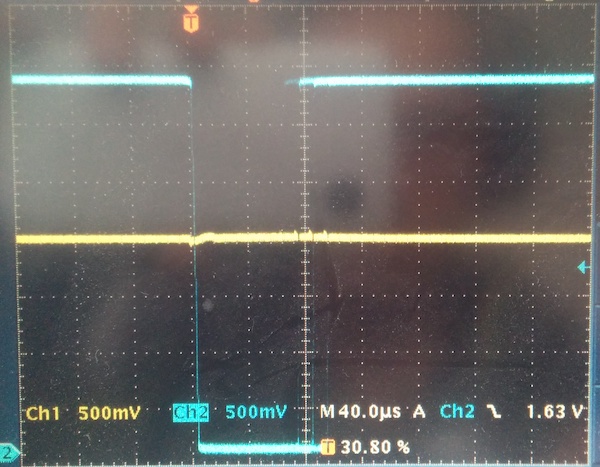
The signal edges are faint, but you can tell from the high/low levels that the signal duration is in the 60–100μs range we expect from Nairol’s reverse-engineering. The potential across the photodiode stays basically zero, which indicates the transimpedence amplifier is working as designed: The op-amp and feedback network are acting as a “virtual ground” and preventing any potential from forming across the photodiode.
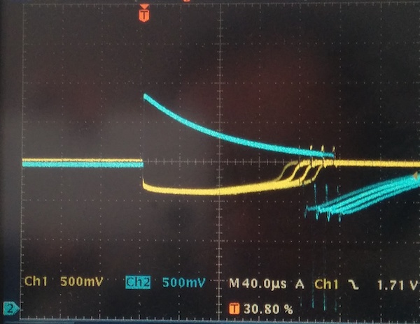
Here’s the signal (blue) entering the comparator; note the predicted exponential decay as the high-pass filter capacitor discharges:
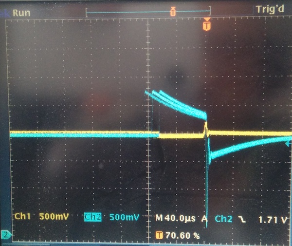
Of course, the more interesting traces are in the case where the signal duration is extended. Here’s the potential across the photodiode (yellow) and the transimpedence amplifier output (blue):
![]()
Note that a potential develops across the photodiode (yellow, roughly -300mV), which indicates that the op amp and feedback network can’t keep up with the photodiode current. Also note the DC offset of the transimpedence amplifier output, about 2.5V (from ambient light, presumably). Also note the signal duration — the shortest is 160μs, which disproves my earlier hypothesis about the problem being the RC filter. (“Look at the signal on both sides of the high-pass filter; if the output isn’t delayed, it’d disprove this hypothesis.”)
For completeness, here’s the signal after the RC filter (going into the comparator):
Revisiting the amplifier current question
By seeing a potential develop across the photodiode, we know the op amp must not be able to source enough current to cancel the photocurrent. Where did I go wrong earlier?
Probably because I didn’t do any actual analysis, I just noted that the expected photocurrent was less than the rated output of the op-amp.
Specifically, what I missed is that the op-amp output current must first go through the feedback network before it can cancel any photocurrent. With a 3.3V max output voltage and the non-inverting terminal ideally at LVCC (half 3.3V), Ohm’s law gives the max current across the resistor:
$$ I = \frac{V}{R} = \frac{1.6\,\mathrm{V}}{100\,\mathrm{k\Omega}} = 16\mu\mathrm{A}. $$
which is less than the ballpark 50μA max photocurrent.
Well, that explains why Johnson recommends using the smallest gain resistor necessary to get an output voltage above 100 mV. It also explains the sub-optimal behavior when the receiver circuit is too close to the lighthouse.