Last newsletter we asked “how fast can plants grow?” and I was unsatisfied with the 20x gap between my rough estimate and reality. Thanks to those of you who pointed out to me plant respiration, where carbon is lost as CO2 due to various plant metabolic processes (especially those occurring at night, when the CO2 cannot be recaptured by the plant via photosynthesis).
Flexures
I’ve spent the last month doing the opposite of back-of-the-envelope estimation: Actually trying to make something work well.
For a yet-to-be-disclosed project, I need a satisfying-feeling axis of rotation — think “knob feel” from a 1970’s stereo.
Normally one might turn to bearings, basically two concentric rings that can rotate with respect to each other. However, in my case I need an attachment point that is separate from axis of rotation.
Since I have weekend access to a 50W CO2 laser cutter, I figured this would be a perfect opportunity to explore flexures (AKA compliant mechanisms), which are fabricated from a single material with geometry designed to bend only in certain degrees of freedom.
In particular, I figured I’d try this “butterfly” flexure from a wonderful video overview, which is fixed only at the bottom but rotates around the center:
I roughly drew a similar design up in CAD:
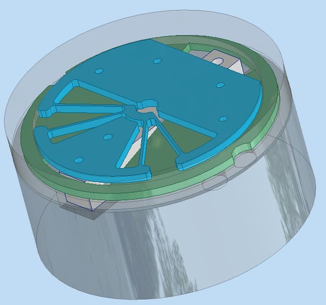
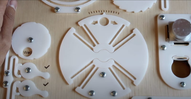
and spent a weekend cutting acrylic and tweaking angles/thicknesses to try and find a satisfying feel:
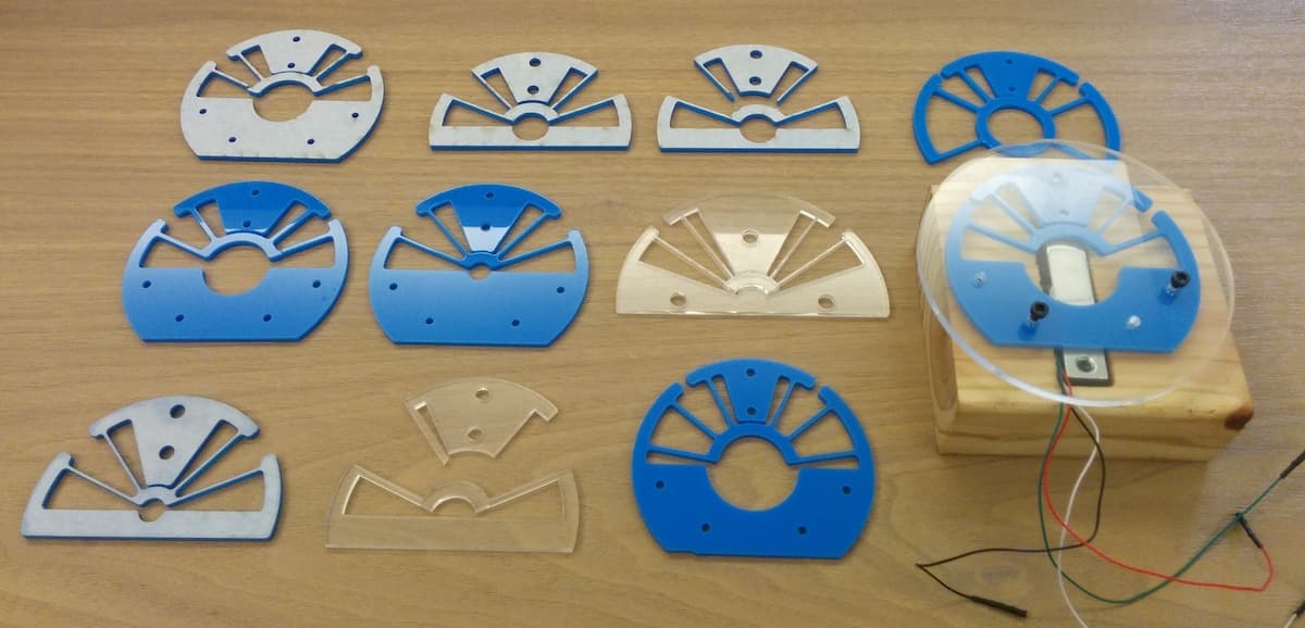
You can see where this is going, right?
I quickly put down my original project to the side to further investigate flexures.
To understand why the butterfly flexure moves the way it does, I read up on FACT, a theoretical framework for designing flexures. This involved a lot of staring at what I presume are some of the trippier figures which’ve appeared in the journal Precision Engineering:
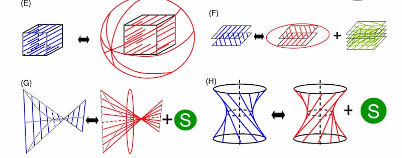
until I (thank God) found the author’s far more comprehensible YouTube lecture series. (See lecture 1 for an intro, skip the math of 2 and 3, then watch lecture 4 for the big concepts and sweet pictures.)
Of course, this schematic/conceptual design is only half the story. Given that I already have a the butterfly flexure in mind, how do I go about optimizing the geometry to get a robust, skookum-feeling rotational mechanism?
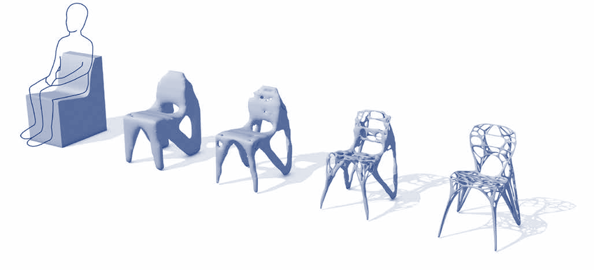
This is refreshingly different from popular “generative-design” approaches which iteratively remove unstressed material from parts so you can save 5g of aluminum in exchange for an extra $100k of manufacturing costs and weeks of H.R. Giger nightmares. You know, this stuff:
In contrast, my flexure geometric optimization problem has a lot of well-defined dimensions to explore even within the constraints of a cuttable-by-2D-laser design space:
- To increase axial stiffness (for satisfying feel), is it better to use more thin springs or fewer thick springs?
- How do the angles of the springs affect undesired motions (pitch/yaw out of the plane or translations within the plane)?
- How will using other plastics (or laser/waterjet-cut aluminum) affect the motion?
- How does the thickness affect the part motions?
I know that this process is doable in theory:
- Develop parameterized geometric model (sheet thickness, number of springs, their width and position, etc.)
- Generate instances and run finite element analyses (FEA) to find their modal frequencies
- Iterate based on optimization criteria (e.g., maximize stiffness in undesired motion directions and the gap between the desired modal frequency and all the others)
However, I’m not quite sure how to go about it in practice. With a fair bit of pointing and clicking, I can coax my CAD software to visualize geometric modes:
But I’d love to find a free and open source solution upon which I can build a long-term foundation for programmatic workflows.
SolveSpace is a very nice lil’ CAD tool, but (as far as I can tell) lacks variables and other parametric / programmatic support. Maybe I’ll have to script their underlying geometric constraint library?
Or just construct geometry by rendering SVG in the browser? Ehh…
As for the FEA, I have a plethora of choices for both meshing geometry and the physics calculations themselves, but I’ve been unable to find a solution that doesn’t require me to earn a PhD in the process.
FEA for All got me looking at Salome, though it takes an expert-user 30 minutes of clicking to bend a plate. FreeCAD’s workflow is similar and also (in my past experience) crashes often.
The most promisingly straightforward mesh -> modal analysis command-line workflow I found was from a project for designing musical bells, but unfortunately I wasn’t able to compile it on my Mac.
Maybe I’ll just have to bite the bullet and learn enough about the actual statics equations to model/simulate it using FreeFEM?
If you have any favorite geometric parametrization/generation or structural analysis tooling, please let me know!
Misc. stuff
Previously we discussed working via remote desktop. I finally have a good solution: Use Parsec (Windows hosts with GPUs only, sorry) for remoting and VirtualHere to forward USB peripherals from client to host. I’m doing CAD work with a spacemouse across town and the end-to-end latency is completely tolerable (20ms). Amazing!
“pretty fucked up that eukaryotic and prokaryotic DNA polymerases arent homologous.”
“I made a confocal laser microscope”
See also this home-built scanning tunneling electron microscope.
“You know birds? Imagine if actually there were amphibian birds and mammal birds and insect birds flying all around, and they all looked pretty much the same – feathers, beaks, little claw feet, the lot. You had to be a real bird expert to be able to tell an insect bird from a mammal bird. Also, most people don’t know that there isn’t just one kind of “bird”. That’s what’s going on with trees.”
“vegetable oil is now the most consumed food in the world, after rice and wheat”
“there aren’t many cases that are full-out war, where 7-Eleven is this set on crushing someone.”
“The fact that we collectively don’t see it as a colossal moral failing that we haven’t figured out a way to get our work done without having to routinely cut corners in the rush for fame and fortune is deeply troubling.”
“bigmouth buffalo exhibit negligible senescence in multiple physiological systems despite living for nearly a century.”
On cheap, mm-scale, crystal and passive component-free integrated circuit radios that can chat standard Bluetooth; also a 8000 node, city-block-sized wireless network with sub-ms time synchronization and total power budget (over all nodes) of less than 8 W.
A podcaster designs and produces a custom pasta shape.
Also: “pasta that can be flatly-packed, and pop into different 3D shapes through a self-folding process upon water hydration.”
“How do I escape though the rear door of a Tesla in the event of a power failure?”
“Maybe your cryptocurrency is different. But look: you’re in really poor company. When you’re the only honest person in the room, maybe you should be in a different room.”
“Since 1973, when the first death penalty laws now in effect in the United States were enacted (8), 143 death-sentenced defendants have been exonerated.”
“DANNCE is the markerless 3D tracking system you’ve been waiting for” (especially if you study animal behavior)
The NYC school system runs a budget that is about the same as the entire NIH.
“Significance testing did not spring fully formed from the heads of these men. It was crafted and refined over the years specifically to articulate evolutionary and eugenicist arguments. Galton, Pearson, and Fisher the eugenicists needed a quantitative way to argue for the existence of such differences, and Galton, Pearson, and Fisher the statisticians answered the call with significance testing.”
“These files are never used for anything inside Signal and never interact with Signal software or data, but they look nice, and aesthetics are important in software.”
Seconde-Seconde makes fun watch hands and has a lovely website.
“the whole idea of a personal carbon footprint was a targeted BP media campaign in 2005 and it worked so well that it seems like we’ve all forgotten this”