A spin-coater from SLA-printed parts
← Back to Kevin's homepagePublished: 2021 Nov 4I built a spin-coater from $35 of parts to deposit glue on microscope slides:
Background
I wanted to replicate a paper describing a millifluidic system built from a glass slide glued to a PCB:
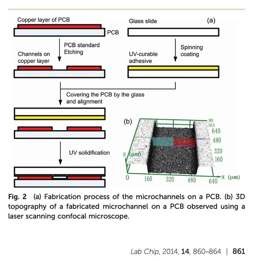
The glue layer needs to be thin so it doesn’t block the ~100um deep channels. Thin layers can be made by “spin coating”; essentially spinning the glass slide at a few thousand RPM, adding a drop of glue, and letting centripetal force spread out a thin layer across the entire slide.
Rather than buy a commercial spin coater with precise RPM control, I decided to build something from a cheap drone motor, following
Applied Science’s video overview
Stefik group’s lab notes
Jeff McBride’s notes
Design 1: Vacuum hold-down
Following the Stefik group, my first design pulled a vacuum through a drone motor’s hollow shaft:
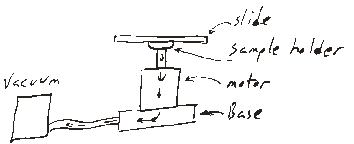
It consisted of two parts:
A base into which the motor could be fixed and attached to a vacuum hose.
A sample holder, which screwed directly into the motor’s M5 x 0.8 shaft and provided a surface unto which the slide could be, uh, sucked. Amazon review hearsay suggested my lil’ $20 vacuum pump pulls 20 inches of mercury (70kPa; 10psi), which for a 16mm diameter vacuum area yields about 3 pounds of force — not huge, but plausibly enough to keep a glass slide from flying off.
I used an MSLA 3D printer to fabricate both parts, which both went through several iterations:
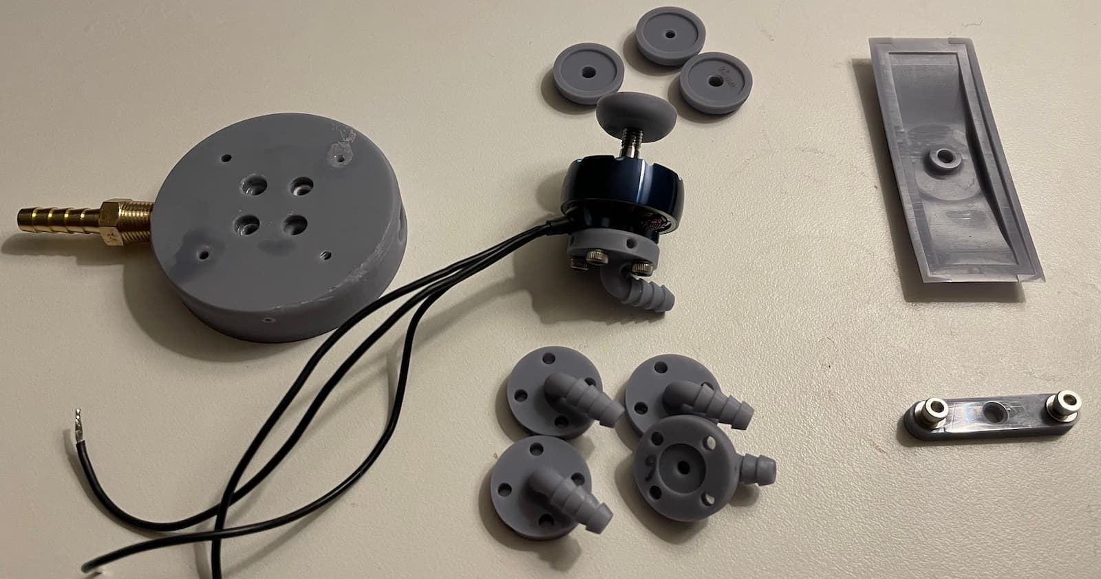
For the base I originally printed a large piece (left) into which I could screw both the motor and a common brass hose barb (for the vacuum).
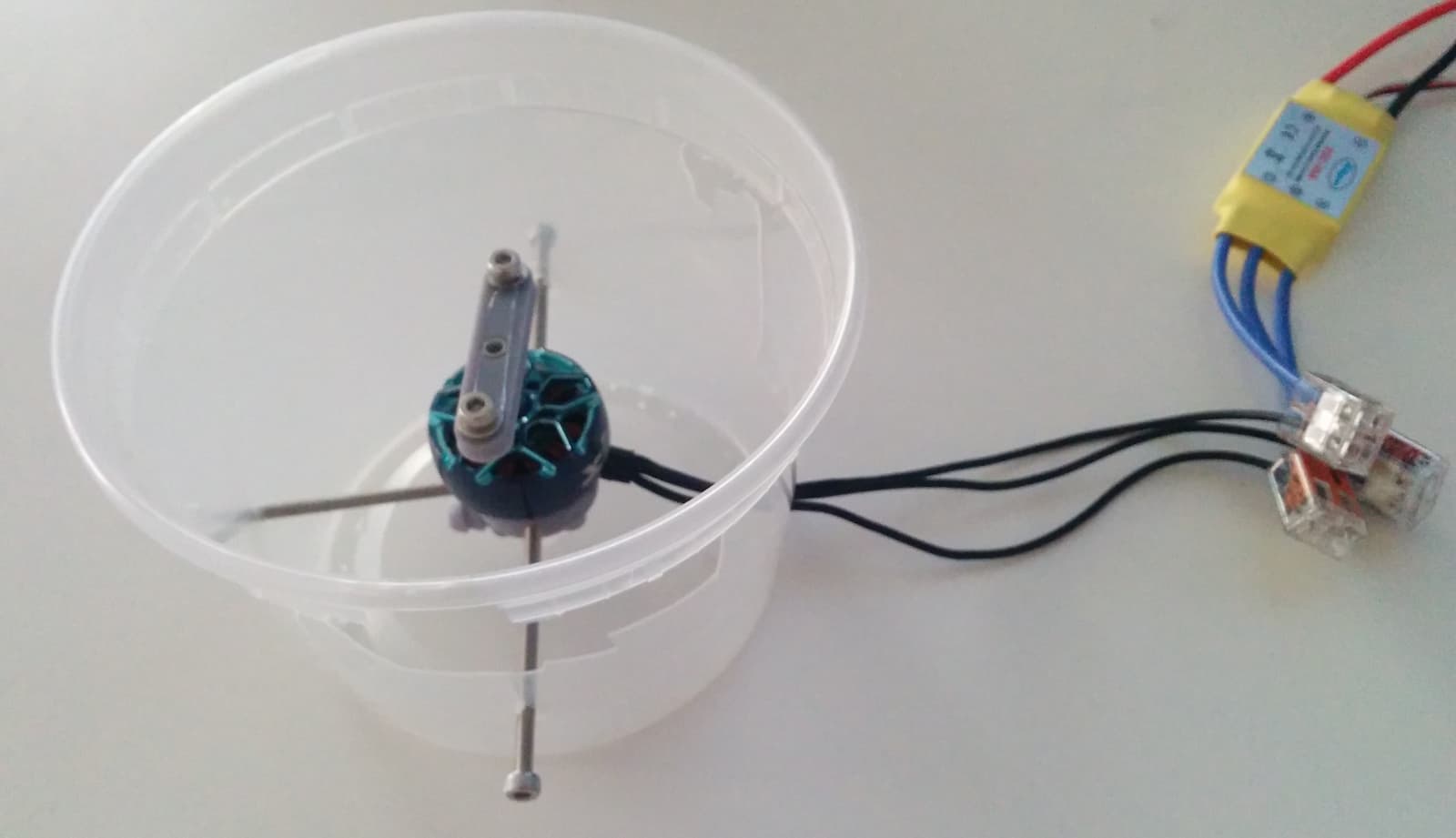
In waiting for the barbs to arrive, I realized I could — duh — just print my own, and furthermore, could shrink the part by using long screws to “hang” the entire assembly within a plastic takeout container. This yielded the base design at bottom center.
Unfortunately, I wasn’t able to pull a vacuum. I redesigned the parts several times to incorporate o-rings (see Vacuum Seals Design Criteria - NASA Lessons Learned) and increase the vacuum hold-down area (sample holder at top right) before it occurred to me to hold the assembly underwater and blow air through it, which revealed that the motor bearing itself it was leaky. (Presumably the Stefan group either got lucky with a more airtight motor bearing or simply have a more powerful vacuum.)
In frustration I printed a “let’s just hold this down with washers”-style clamp (bottom right). Spinning this, I quickly discovered that:
- Glass microscope slides (1 mm thick) don’t appreciate being held down with M3 washers at just two points
- Polypropylene takeout containers are not, in fact, impact-resistant
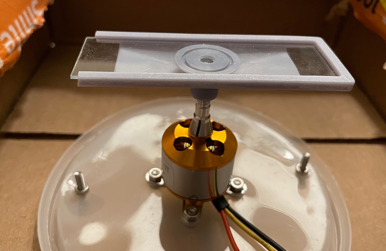
Design 2: screw clamp
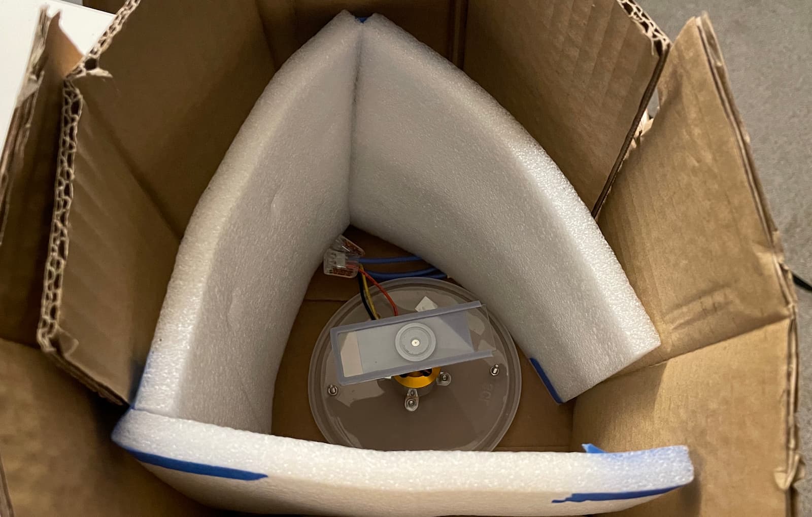
For the second design I vastly improved the safety characteristics using cardboard and foam:
and switched to a slower 1000 Kv motor from the original 1755 Kv hollow-shaft “racing” motor. (Nominally, 1 Kv = 1 RPM / Volt for an unloaded motor, so at 12 V the 1000 Kv motor has a top speed of 12,000 RPM.)
The slide is held captive at the outside edges and “clamped” from underneath by one of the earlier holder designs (sans o-ring). Twisting the outside holder clockwise presses the slide against fixed circular piece on the shaft.
I intended to insert the slide from underneath and hold it on all sides, but there wasn’t enough clearance / flex, so I cut off one side of the holder and side-loaded.
Control + performance
The motor came with a documentation-less electronic speed controller (ESC), presumably for use with…whatever electronic stuff the remote controlled model airplane people use. According to Internet lore, the ESC expects a 50 Hz PWM signal on the white wire, with a 1 ms pulse corresponding to zero-throttle and a 2 ms pulse for full-throttle.
I used a $4 stm32f401 breakout board to generate this throttle signal from a hardware timer.
Unfortunately, I left my box of satisfying linear potentiometers in Taipei, so I had to settle for controlling the motor speed with an <input type="range"> via WebUSB.
My scope is still in Taipei too, so I bought a $13 logic analyzer to verify the throttle signal was correct.
The ESC can be calibrated by sending a full-throttle signal at power-up, waiting for it to beep, then sending the zero-throttle signal.
My motor only starts spinning at about 10% throttle, where it immediately ramps to about 3800 RPM (according to a $25 digital tachometer). I went as high as 14% throttle, which gave 4600 RPM and is, honestly, as fast as I want to spin a glass slide in a cardboard box on my desk.
Bill of Materials
| Part | Cost | Note |
|---|---|---|
| 12V vacuum pump | $23 | |
| 12V power supply | $12 | The vacuum pump draws 12W and motor probably similar, so any 5A supply you have laying around will be plenty |
| hollow shaft drone motor | $22 | iFlight XING2 2306 1755KV 6S FPV Motor Unibell (lowest Kv hollow-shaft motor I could buy as a single) |
| speed controller | $19 | powerday XXD A2212 1000KV Brushless Motor + 30A Speed Controller |
| o-ring assortment | $0.01 | |
| m3 screws (short bois; long bois) | $0.10 | |
| 6mm ID silicone tubing | $11 | |
| stm32f401 breakout board | $4 | You’ll need a programmer too |
For wiring, I recommend these great Wago 221 connectors and Klein Tools 11063W wire strippers. You’ll want solid-core wire that you can poke into solderless breadboards.
Also: When you buying microscope slides online, don’t include a cast iron vise in the same order. Trust me on this one.
MSLA printing process + tips
This project was my first time designing 3D printed resin parts. I’ve been shocked by the quality of parts made from $40 / 1 kg resin on a $500 Elegoo Saturn printer: Tolerances are all within 0.1mm and I can reliably print fine (0.5mm pitch) M3 threads. Print time is driven only by part height; the 16mm tall parts for this project took ~1 hour to print.
While there’s plenty of “my first SLA printer” YouTube content, it’s mostly focused on figurines of, uh, busty warrior elves rather than functional parts. To save you from such horrors, here’s the process that’s working well for me:
- Design parts in Autodesk Inventor and export to STL.
- “Slice” in Lychee Slicer.
- Transfer to Elegoo Saturn via USB thumb drive and print.
- Put on nitrile gloves and respirator with organic vapor cartridges.
- Remove part(s) from build plate using the metal scraper included with the printer.
- Rise part in isopropyl alcohol in plastic pickle container, using toothbrush to scrub.
- Second rise in clean(er) isopropyl alcohol jar.
- Submerge part in water (in transparent take-out container), and post-cure 5 minutes in UV curing chamber.
- Done!
Modeling threads in CAD: I use Autodesk Inventor for CAD, which doesn’t actually create geometry for “thread” features. (Which is understandable, as most of the time threads are cut with taps, not machined or otherwise manufactured “directly”.) To actually create thread geometry, I’m aware of two options:
CoolOrange ThreadModeler is a plugin that converts thread features into geometry. Unfortunately, it’s not quite parametric; if you change the original hole diameter or depth, the plugin-generated features won’t automatically update — you have to delete them and start over. This was a dealbreaker for me.
Follow this CAD Whisperer video to design a reusable “sheet metal punch” / iFeature. I never would have explored the clunky iFeature abstraction mechanism without this video, but after pushing through, it’s clear that this will come in handy for reusing parametric geometry for captive nuts, o-rings, microfluidic ports, etc.
Inaccurate z-dimension when printing directly on build plate: Out of the box, my Elegoo Saturn MSLA printer “shrunk” the first few mm of parts printed directly on the build plate. Initially I thought this was due to poor leveling, but it turns out that it’s a design flaw in the z-axis assembly which can be calibrated out in g-code according to these instructions.
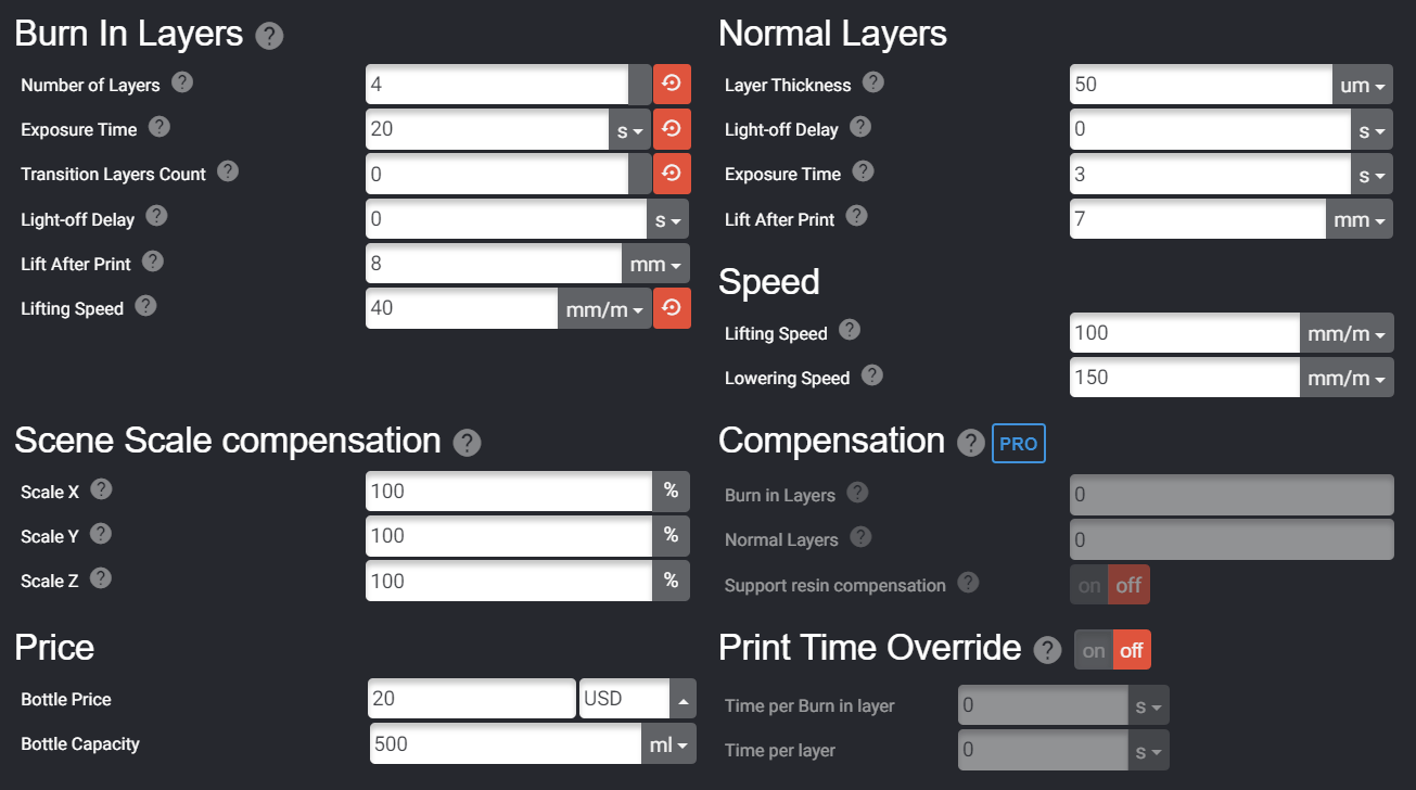
Lychee Slicer Exposure Settings
Bed leveling: Instead of following the manufacturer-provided instructions to level on card stock, I level the build plate directly on the FEP. (Removing the vat and cleaning the build plate just to level is too much work!)
The UI here is a bit confusing, here’s my process:
- Confirm there are no chunks of cured resin in the vat, as these could crack the LCD screen.
- Loosen build plate right-side screw.
- Loosen build plate front screw.
- Confirm build plate is loose and can spring upward (if it can’t spring, leveling might crush the LCD screen).
- Press “Home” button to move z-axis to hardware optical limit switch.
- Gently hold build plate down, centered in resin vat (not twisted).
- Tighten front build plate screw.
- Tighten right-side build plate screw.
Mind the temperature: I had problems with prints sticking to the FEP, even after leveling the bed. These were resolved by pre-heating the resin (rated at 20–25 C) to at least 70 F. My entire printer is in a small apartment closet, so on cold days I throw a cute 1500W space-heater in there for 10 minutes before starting a print.