Designing a flatpack bed
I just moved into an unfurnished apartment and my professional woodworker friend just got a plywood-sheet-sized CNC router, so I’ve been designing myself a bedframe. The rough scope / requirements:
- fit a 200 cm x 180 cm mattress
- have 50 cm of clear space underneath for storage
- visually hide this space from the front (required) and sides (nice-to-have)
- CNC-cuttable from a single sheet of baltic birch (2440 mm x 1220 mm)
- maybe use Ikea LÖNSET slats
Christoffer Martens’s Siebenschlafer bed is probably peak flat-pack brutalism:
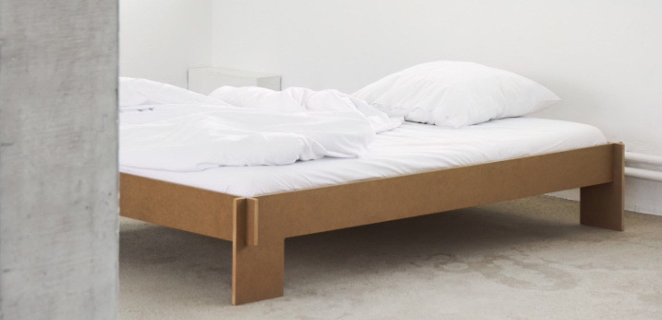
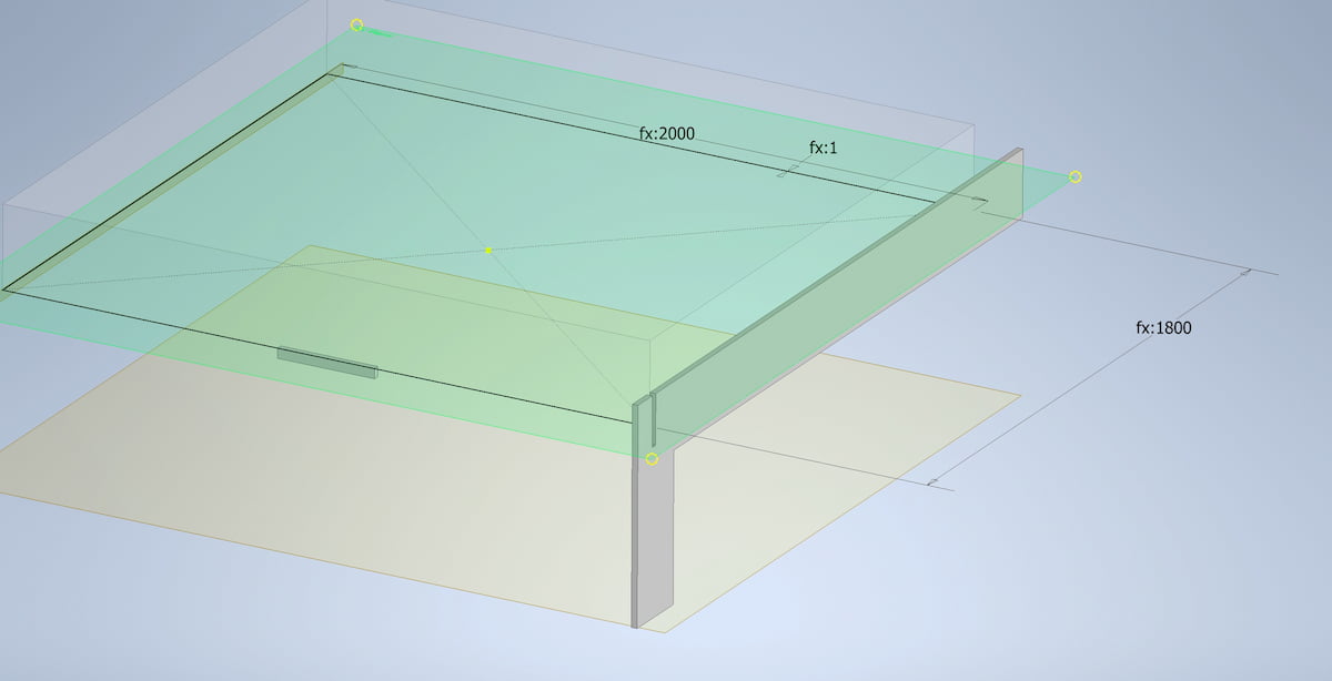
I had a go at making a taller version for myself in CAD:
but it became clear that this minimalist design definitely won’t hide the multitude of boxes we’ll be storing underneath.
(Also, while I’m not a super Bauhaus fan, I am somewhat irked that this minimalist design relies on glued/screwed internal rails to support the bed slats, rather than expressing that core functionality externally.)
Since 18mm 13-ply CP/CP Baltic birch is €150/sheet (thanks Putin), rather than throwing more wood at the problem, I’m trying to come up with a design that leans into precise, complex cuts enabled by CNC — perhaps some kind of frame skeletons that can be covered with rattan or fabric to hide the under-the-bed mess.
As always, I’m open to design ideas and suggestions if you have any!
Flatpack CAD
I used Autodesk Inventor to play with the Siebenschlafer design, but I found it a bit tedious. In particular, ensuring that all my parts could be cut from a single sheet:
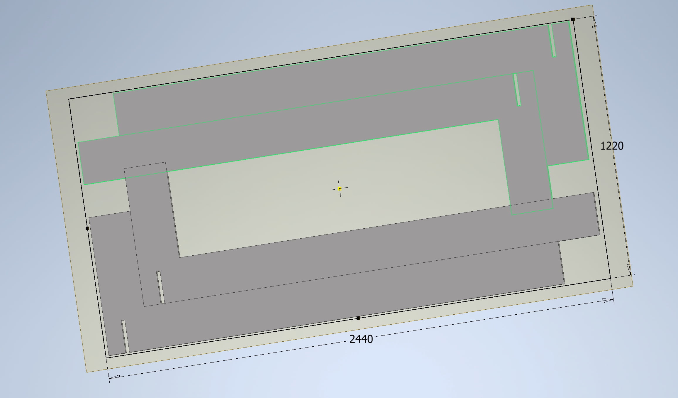
The process for doing that is, roughly:
- Create multiple solid bodies in a single part file.
- Use the “make components” button to export all of these bodies into their own part files (which, thankfully, remain linked to the “main” part file).
- Import all of these parts into an assembly file.
- Outline the plywood sheet in the assembly file.
- Assemble everything using explicit constraints (each part must be constrained to the XY axis, some faces made parallel to each other with some cutting offset, etc.)
It reminds me a bit of programming in Rust, actually — yes, there are some situations where I want this level of explict control and detail, but right now, dude, I’m trying to roughly explore the design space. Just let me quickly push some stuff around!
Of course, Inventor, Solidworks, etc. are general-purpose CAD tools for mechanical engineering in 3D, and arguably there’s a trade off between generality / power and the fluidity of use. This got me curious about what tools might exist out there optimized for this kind of 2D cutting and part design?
E.g., CutList Optimizer is a lil’ gem of a web app calculator for cutting rectangular sections from sheet stock.
Cuttle.xyz
Cuttle is a slick web-based 2D graphics editor with reusable components that’s quite code-forward. The backstory is interesting too: It started with Toby Schachman’s 2015-ish Apparatus research project, grew at Dynamicland, and spun out as a company in 2020. (Apparatus is open source, but Cuttle is not.)
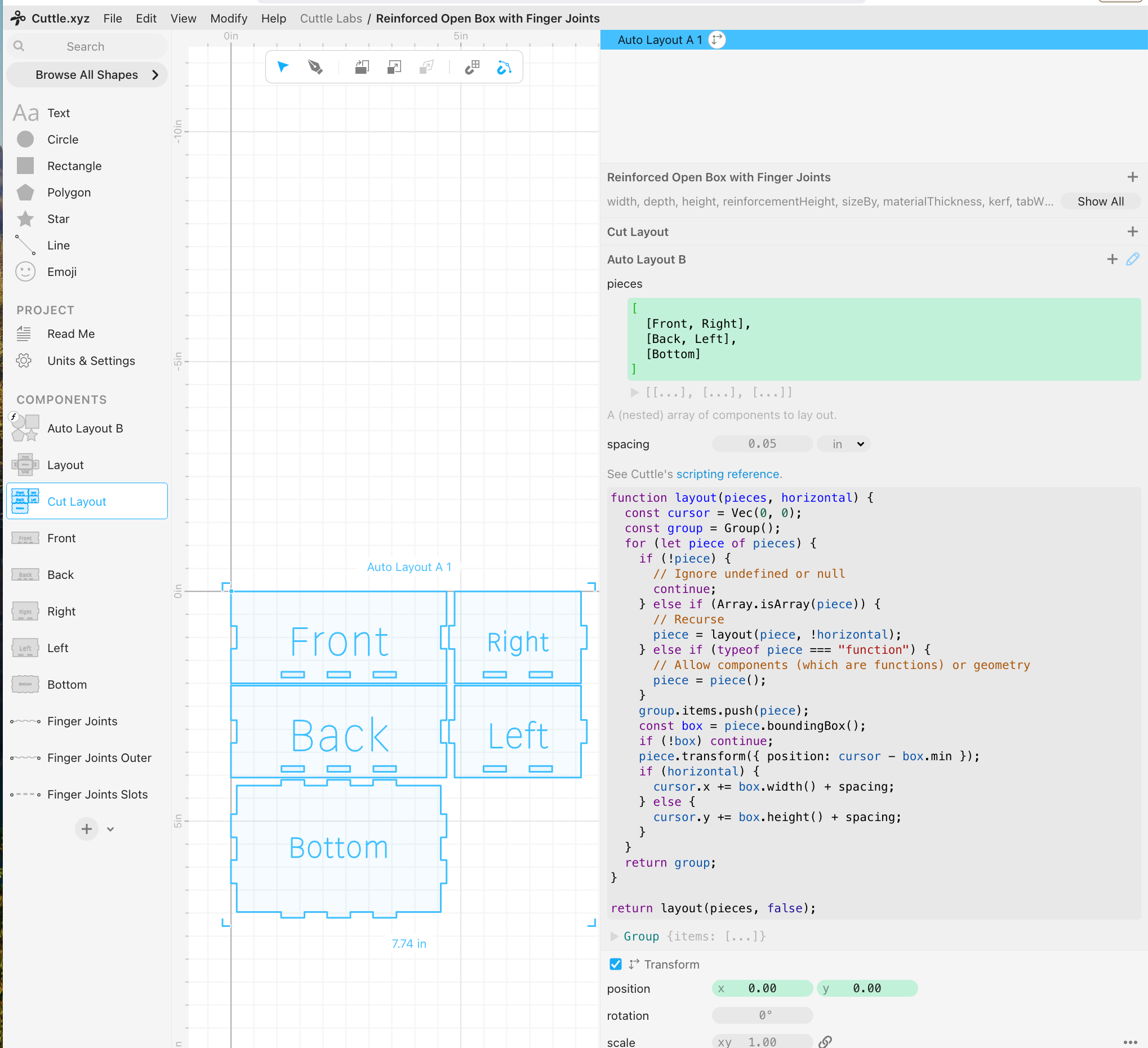
solves the “linked view problem” using a component system:
- Each side of the box is a component
- A “layout” component instantiates each side in an “unfolded” arrangement
- A “cut layout” component uses a layout algorithm written in JavaScript to tightly pack the components to be cut out from a sheet of material.
Conceptually there’s a lot of overlap with tradCAD’s Assembly-of-Parts model, though having a programmatic autolayout routine directly in the tool is nice when it finds reasonable solutions. (Though something beyond naive, end-to-end bounding-box layout would be needed for my situation — it’s on my TODO list to try out sparrow, a Rust crate for “State-of-the-art Nesting for 2D irregular strip packing”.)
FlatFab
FlatFab is an open-source academic project from 2014 (presention video) for interactive modeling with planar sections. It appears to be more art rather than engineering/mechanism oriented, as there aren’t e.g., constraints or numeric parameter inputs. The interactions look pretty clever, as they’re oriented around quickly creating new “slices” via sketching and reorienting the camera to perpendicular perspectives on which the next interlocking slice can be created:
I’m also impressed this 11-year-old academic project is still being maintained — one of the original authors is still accepting PRs and cutting new releases as of 2024.
Kyub
Kyub started as an academic project from the Hasso Plattner Institute (2019 PDF) and has a very slick workflow for making laser cut box beam objects:
(Note the cute physics when they flip the chair over! Someone clearly appreciates game design.)
The professor’s team seems to have used this as a platform to explore lots of ideas:
- FoolProofJoint: Reducing Assembly Errors of Laser Cut 3D Models by Means of Custom Joint Patterns
- AutoAssembler: Automatic Reconstruction of Laser-Cut 3D Models
- Roadkill: Nesting Laser-Cut Objects for Fast Assembly
- assembler3: 3D Reconstruction of Laser-Cut Models
Unfortunately, as far as I can tell the software isn’t open source, nor is it easily available to try. The Kyub.com website suggests it’s a company, but all of the copy and examples reference academic stuff; no pricing page, just a mention of funding from Postdam in 2024. The chief architect (masters student?) has it on their CV from 2016–2019, so I’m not sure whether the software is still under development.
Joinery
Joinery: Parametric Joint Generation for Laser Cut Assemblies is a 2017 paper on a system for interactively matching sections of 2D shapes and creating a varitey of joint profiles:
The implementation is open source, but hasn’t been updated since 2017, so I suspect it’s more an academic exploration than something actively being used.
Both this and Cuttle are natively 2D, which forces the designer to mentally “unwrap” their designs to accommodate the software.
OnShape feature scripts
OnShape is a cloud-hosted professional CAD tool built on Parasolid, so it’s the more tradCAD than the previous academic/indie projects. However, it has a robust programmatic extension mechanism (“FeatureScript”), which third-parties have used to create reusable laser cut joint geometry. In this example:
- a part is modeled with multiple bodies having overlapping geometry
- then a FeatureScript is used to automatically create finger joints
- another FeatureScript is used to layout all of the bodies and a DXF exported for laser cutting:
See this OnShape forum thread for more details.
Mozaik
I ran across this professional cabinet-making software in a few woodworker forum posts. The landing page has that generic “private equity bought us out and changed to a subscription model” vibe, with no screenshots or detailed usage information about the software itself. However, I did find this recent video on the company’s YouTube demonstrating how to design a desk:
The software looks like a dog’s breakfast of modal dialog boxes specific to cabinetry, and the process of modelling a desk felt impressive to me in the same way that I’m impressed when, e.g., someone creates Minesweeper using only CSS.
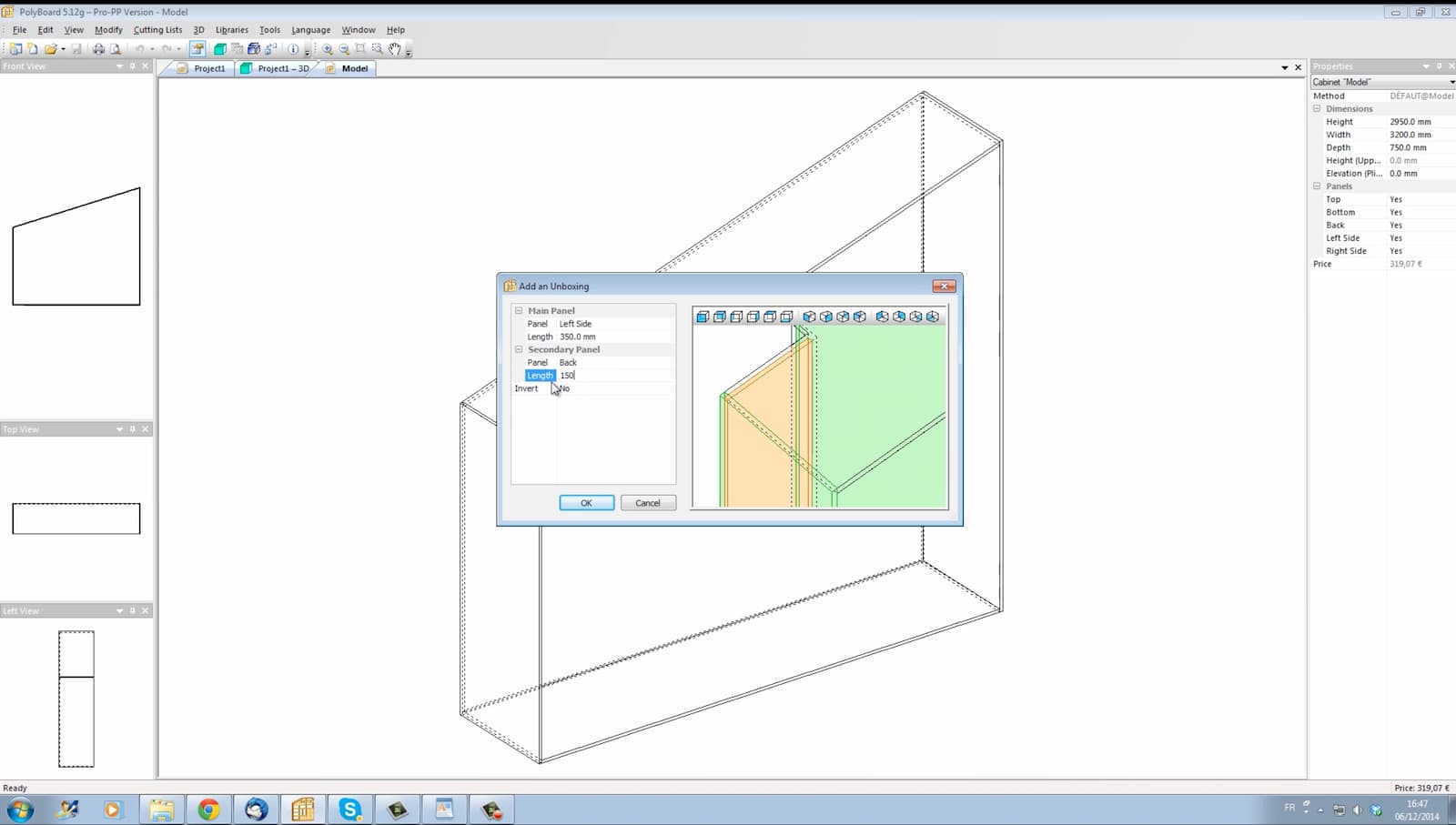
Polyboard
Polyboard is another professional cabinet-making software, though with a much more informative landing page. Their 12-minute demo video outlines creating a complex built-in cabinet with shelves, drawers, etc. Conceptually there appear to be lots of cabinet-specific operation — like this “unboxing” tool to make room for a wall column by insetting the corner of a cabinet:
The panel joinery is done by designating as overpassing/underpassing and then selecting the type of joint (mortise and tenon, miter, etc.).
There’s also some abstraction capabilites in terms of project-wide “stylesheets” for materials and joinery methods.
The software automatically generates nice manufacturing output artifacts like cut sheets, labels, etc.
The same company also sells OptiNest software for arranging parts for cutout, taking into consideration additional constraints like matching grain (cutting panels in the same position and orientation as the final design, so that, e.g., drawer faces are visually continous) and using previously cut panels.
I have no idea how much this software costs, but it’s sold with a lifetime license + support contract model and if I ran a cabinet shop this is probably what I’d be using.
LSP bidirectional editing + CAD conceptual models
James Vaughan wrote about my idea from last newsletter to use LSP to connect a textual code editor with a graphical interface, and the HN comments were a good read. It was fun to discover Jason McGhee’s livelove, which does exactly what I’ve been working on in my system:
“Live coding” here means, when you change the code, you’ll see the changes reflected instantly / as you type them. If there are errors, it’ll use the last valid code.
“Live feedback” here means, you’ll see every value of variables you created, updated live, next to any reference to it (as an inlay hint).
(For more on LSP: Matklad on the real innovation is that it got people to expect more functionality from their editors and all the ways in which the protocol could have been better. See also Michael Peyton Jones on LSP: the good, the bad, and the ugly.)
I also had a great discussion with a visual-programming-maximalist friend of mine, who lamented that every project he’s seen with code + GUI bidirectional editing ends up having all of its functionality embedded in the code part, leaving the GUI a “glorified livereload or data-entry device”.
That matches my experience too, and I’m not sure whether this:
- reflects something fundamental — e.g., it’s easier to express and manipulate complex abstractions with textual language, or
- reflects a historical contingency — computer programming happened to skew textual, so the people building new systems are selected for textual affinity and tend to propagate it.
Most of my object-level CAD practice (i.e., actually designing and manufacture stuff) has used GUI tradCAD tools (with one or two minor forays into their APIs, like when I did automatic keyboard switch placement in Autodesk Inventor).
So a large part of the motivation behind my current codeCAD work is to explore this question: if tradCAD is 90% visual with 10% parameters/code/abstraction bolted-on, what does it feel like to have 90% code/abstraction with 10% of visual sketch input (glorified data entry)?
It remains to be seen which one I’d actually prefer in different contexts.
Another idea that my friend raised is the distinction between:
- code as primary artifact, where there’s a single concise, expressive, human-readable “program” that generates the geometry and GUI tools are limited to manipulating that code artifact.
- code as log, where the primary artifact is some opaque data structure (binary saved file) which can be manipulated by either GUI or code. Many successful CAD tools (Blender, for example) “echo” all the GUI operations to a command history as code, which makes it easy to discover functionality and switch between GUI and code depending on context.
Finally, writing this newsletter and exploring the 2D CAD tools above got me thinking about CAD domain models. I don’t mean the geometry model (triangular meshes, B-rep, signed distance fields, etc.), but rather the concepts and “universe of discourse” that a tool provides for designers to think about their problem space and express possible solutions.
- tradCAD emphasizes a “feature tree” of operations like extrude, revolve, chamfer, fillet, etc., each of which references faces/edges/vertexes of existing solids or 2D sketches. Sometimes these tools also have specialized higher-level modes like “pipe designer” and “frame generator”.
- “Constructive solid geometry” emphasizes using boolean operations (union / intersection / difference) to combine spheres, prisms, cones, etc. into more complex designs. It’s straightforward to understand, available in most geometric kernels, and is the primary model of simple tools like OpenSCAD and Tinkercad.
- the industry-specific software discussed earlier is all in terms of cabinet carcasses, shelves and miter joints; the underlying geometry (and the kernel itself) is mostly hidden implementation detail.
- simulation/CAM tools emphasize the manufacturing operation themselves. E.g., in FullControl GCode Designer instead of designing abstract geometry one instead works in terms of the extruder tool path and extrusion rates.
I’m reminded of the Alan Perlis quote:
A programming language is low level when its programs require attention to the irrelevant.
The trick of designing a fluid, powerful, and fun CAD system (or any design tool) is that what’s relevant is inherently contextual.
When I’m exploring the idea space, I just want to loosely try out ideas to see what might be possible. I want to loosely say “yeah, some way of attaching this to that, some sort of hinge here, etc.”
Only later, when I’m ready to converge and start filling in the details of a design, will I decide on, say, screws.
And then, perhaps even later, once I’ve decided to 3D print with some particular filament and layer size, will I be ready to think about installing threaded inserts, tapping plastic, or 3D-printing threads.
When I started sketching out my lil’ codeCAD language a few months ago, I expected to follow the tradCAD conceptual model, but after seeing some of these more specialized workflows, reflecting on the sorts of parts I’ve been making, and (to be honest) being somewhat daunted by the design challenges of the topological naming problem, I’m wondering if I might have more success with something closer to a parametric CSG approach.
Only one way to find out…
Misc. Stuff
I made a simple script to map three dials on my $60 MIDI controller to the brightness of my three monitors, so I can easily adjust what I’m focusing on or turn them all off completely when I want to just write at my desk. It is immensely more satisfying to turn a dial than to faff with moving the mouse around and hitting a keyboard button for each monitor.
My first pass invoked a command line program to adjust the monitor brightness, but this turned out to be noticeably slow (~100ms each time you invoke the program), so I had to speed it up with…HTTP (!?!). Notable that tactile input mechanisms push me to make software itself faster.
I recently implemented click-to-add-a-point, which involved adding and transforming nodes within my codeCAD’s abstract syntax tree. I explored a few options and ended up refactoring my AST so I could operate on it with Clojure Zippers. If you want to do this with a general programming languae, though, you probably won’t have to mess with all of the machinery yourself — for an overview, see refactoring with Codemods to Automate API Changes.
VDO.ninja is an open source, self-hostable “modern Swiss Army knife of audio and video transmission”. If you ever wanted to send someone a no-nonsense, login-free URL with a live video feed of one of your monitors or or the camera input from your phone, this is what you want.
Zencan is a nice looking CANOpen framework for Rust made by my friend Jeff — check out this demo video of using a joystick to scoot a magnet around via planar 2D stepper motor (I’m proud to have originally nerdsniped Jeff back in 2021).
The 3rd Most Important Invention In Human History. A great history and overview of weaving and knitting.
grep.app is fast, as-you-type search across code on GitHub.
Andy Matuschak: “This is an appreciation thread for EuterPen, a multimodal music notation system by @Vincent_Cavez et al. It aims to support the non-linear process of exploration during composition. It’s the most sensitive and imaginative academic HCI design work I’ve seen in quite some time!”