Pinfigurator Language
← Back to Kevin's homepagePublished: 2022 May 22Last updated: 2022 May 31Abstract
Pinfigurator solves for a set of microcontroller requirements (“I need a 3 digital input pins and one output pin mapped to a 10kHz PWM signal”) by finding a specific hardware configuration (“you can use pins pa1, pa3, and pa7 as inputs and timer tim3 for PWM output on pb2”) and generating minimal register initialization and run-time interface code to implement it.
Requirements are specified as first-order logical and arithmetic relationships between microcontroller peripherals, registers, fields, and associated numeric constants (e.g., clock prescalers, timer reload values) and satisfying configurations found via an SMT solver. Alternative configurations may be enumerated via counter-example guided iterative synthesis.
See also earlier work on a web interface for searching across microcontroller devices.
Pinfigurator is not open-source, but feel free to email me if you’d like to discuss your use case.
Background
Microcontrollers are tiny computers with special hardware peripherals (input/output pins, voltage sensors, amplifiers, etc.) controlled via memory-mapped registers. These registers are divided into one or more fields (contiguous subsets of the register’s bits), each of which has a value interpreted according to a predefined schema (boolean, integer, enumeration variant, etc.).
For example, page 311 of the stm32g4 reference manual describes the AHB2 peripheral’s clock enable register RCC_AHB2ENR:
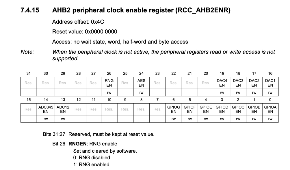
Bit 26 of this 32-bit register controls whether the hardware random number generator is activated.
In a C program, you might activate the random number generator by importing the manufacturer-provided header which defines addresses and bitmasks:
#define RCC_AHB2ENR_RNGEN_Pos                (26U)
#define RCC_AHB2ENR_RNGEN_Msk                (0x1UL << RCC_AHB2ENR_RNGEN_Pos)  /*!< 0x04000000 */
#define RCC_AHB2ENR_RNGEN                    RCC_AHB2ENR_RNGEN_Msk
and then do some bit-twiddling:
uint32_t old_val = RCC->AHB2ENR;    // Read the current register value
old_val &= ~RCC_AHB2ENR_RNGEN_Msk;  // Clear the field
old_val |= RCC_AHB2ENR_RNGEN;       // Set the desired field value
RCC->AHB2ENR = old_val;             // Write back to register
In a fancy language like Rust, you could use a peripheral access crate and its typed API:
let dp = hw::Peripherals::take().unwrap();
dp.RCC.ahb2enr.modify(|_, w| w.rngen().set_bit());
to do the same thing.
Setting registers
We can use Pinfigurator as well. It accepts requirements over stdin:
$ echo '(assert [_ rng enabled])' | pinfigurator
and emits annotated Rust:
pub fn init_registers() {
  unsafe {

    let rcc_ahb2enr = (0x40021000 + 0x4C) as *mut u32;
    //                                              rngen: The selected clock is enabled
    core::ptr::write_volatile(rcc_ahb2enr, 0b00000__1__0__0__0000__0__0__0__0__0__0__0__000000__0__0__0__0__0__0__0);

  }
}
(There’s nothing special about the generated Rust — it’s just a function that writes constants to memory — and it could be in C, Zig, etc.)
To help verify the generated output is correct, it’s designed to be easily cross-referenced with the manufacturer’s PDF datasheets:
- memory addresses are broken out into “peripheral base + register” form
- individual fields within registers are delimited with underscores
- every non-reset field value is annotated with a vertically-aligned comment indicating the field name and value (either enumeration variant, as in this case, or decimal integer value)
As for the input requirements, the square bracket tuple [register field value] is a boolean term (“is register’s field set to value?”) with each component matched against the names and descriptions of microcontroller’s documentation.
If there is any ambiguity, Pinfigurator returns an error:
$ echo '(assert [_ gpio enabled])' | pinfigurator

Lookup [_ gpio enabled] had multiple matches
  rcc-ahb2enr > gpioaen > Enabled: The selected clock is enabled
  rcc-ahb2enr > gpioben > Enabled: The selected clock is enabled
  rcc-ahb2enr > gpiocen > Enabled: The selected clock is enabled
Abstraction
The difficult part of embedded programming is not setting registers, it’s knowing which ones to set. In particular, the ones needed to satisfy high-level design requirements using the pins and peripherals available on a specific device.
Graphical configurators like ST’s CubeMX and fancy type systems like Rust Embedded’s make it easier/safer to implement some configurations, but they don’t help you find them in the first place.
Such configurations can be difficult to find because of hardware limitations. E.g., while most pins can be used for digital I/O, signals from specific peripherals (e.g, a timer’s output or analog-to-digital converter’s input) are available on only some of a device’s pins. The first row of this stm32f0 pin alternate function table, for example:
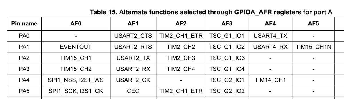
shows that pa0 (first row) can be mapped to one of (columns): USART2‘s “clear to send” signal (via alternate function 1), TIM2’s channel 1 (alternate function 2), etc.
However, when designing a system, I don’t care which pins and peripherals are actually used, just that some subset can be chosen to meet my requirements.
For example, when I made pcb stepper motors, I needed sets of PWM outputs mapped to the same timer (to share a frequency) but on different timer channels (so each pin could have a different duty cycle):
(define-fun pwm-output ((p Pin)) Bool
  (and (driver p tim)
       (signal p #{ch1 ch2 ch3 ch4})))

(def-pin x-a-in1 pwm-output)
(def-pin x-a-in2 pwm-output)
(def-pin x-b-in1 pwm-output)
(def-pin x-b-in2 pwm-output)

;; pins must be mapped to the same timer peripheral
(def-peripheral x-timer
  (= (peripheral x-a-in1)
     (peripheral x-a-in2)
     (peripheral x-b-in1)
     (peripheral x-b-in2)))

;; pins must be mapped to distinct signals so duty cycles can be adjusted independently
(assert (distinct (signal x-a-in1)
                  (signal x-a-in2)
                  (signal x-b-in1)
                  (signal x-b-in2)))
(There’s some new syntax here, just squint at it until we discuss in the next section.)
Specifying these needs directly is much easier than consulting the alternate function tables, finding a satisfying configuration, and implementing in C or Rust myself (“okay, make this pin alternate function 3, that pin alternate function 7, …”).
Furthermore, by keeping requirements at a high-level, as a project’s needs change (add new features, swap pins to simplify PCB layout, etc.), the entire hardware configuration — including the microcontroller itself — can be updated without impacting the application code. (This goal is shared by Rust’s embedded HAL, but in practice I found that device-specific pin and peripheral types/instances always ended up tangled with application logic.)
From an abstraction standpoint, Pinfigurator allows one to discuss not only memory-mapped registers — which C, C++, Rust, etc. can model with the usual pointers, structs, and bits — but also microcontroller-specific concepts. Pinfigurator’s universe of discourse contains the following:
- Peripherals:
tim1,usart3, etc. - Drivers (classes of peripheral):
tim,usart, etc. - Signals:
ch1,tx,rx, etc. - Pins:
pa1,pb2, etc. - GPIO Ports:
a,b, etc. - DMA streams (for stm32f4-series microcontrollers)
These entities are related to each other via total functions and first order logic.
From the example above, the term (driver p tim) is boolean (“is pin p mapped to a timer?”), but non-boolean arities exist too (e.g., (driver p) is whatever driver is mapped to pin p, (port p) is the gpio port, etc.)
Such domain concepts can, of course, can be modeled within a general-purpose programming language, but it’s difficult to prevent such abstractions from impacting code size and run-time performance. (This really matters for microcontrollers, which typically have only few kB of flash memory and are used in applications where microseconds count.)
Furthermore, there is a fundamental impedance mismatch between:
- general-purpose languages, which are designed to compile into machine instructions that can be executed sequentially by a CPU with an instruction pointer, RAM, etc.
- the problem of finding a particular arrangement of a specific microcontroller’s registers, pins, peripherals, signals, etc., subject to some logical constraints and application requirements.
In particular, the problem is “timeless” (solutions can be evaluated without reference to time/order) while general-purpose languages make it nearly impossible to not specify an order. For example, in this typical “initialize, then loop” program:
fn main() -> ! {
  setup_feature_a();
  setup_feature_b();
  setup_feature_c();

  loop {
    run();
  }
}
at runtime the features will be setup in the order written. If the setup routines modify the same registers, then the CPU will read/write those registers multiple times, even if that work is unnecessary (because, e.g., bit twiddles could have been coalesced into a single word-sized write).
The compiler has no way of knowing that the underlying register accesses have been split apart for human reasoning concerns rather than for operational ones — and the programmer doesn’t have a convenient way to tell it. (Understanding memory fences, function inlining, and desperately checking godbolt.org is not convenient.)
While languages like C++ and Rust offer complex compile-time features (template meta-programming, linear types, macros) and LLVM’s impressive optimization passes may reduce or eliminate the run-time cost of some imperative language abstractions (inlining, constant folding, etc.), we might as well just lean into the problem fully.
Rather than (ab)use the compile-time facilities of an imperative language and/or hope we have a sufficiently smart optimizer, instead design a domain-specific tool that:
- allows us to relate domain entities plainly using first order logic (rather than syntax/type/macro cleverness)
- generates code which has obviously minimal size and run-time impact (i.e., synthesized constants)
Syntax
I’m not that interested in syntax, so for my own convenience I designed Pinfigurator around Clojure’s. This is helpful from both an implementation and an end-user perspective, since existing syntax tooling (parsing, transformation, editor highlighting, etc.) can be leveraged “for free”. (However the semantics are not Clojure’s — ultimately things bottom out at SMT-LIB.)
For succinctness, Pinfigurator’s definition forms can include arbitrary predicates, which will be asserted with the binding threaded as the first argument. I.e.,
(def-pin led
  output
  (= pc13))
expands syntactically into:
(def-pin led)
(assert (output led))
(assert (= led pc13))
(Arguably the def- prefix is misleading, as the form is not quite a definition; it’s just a declaration — the introduction of a new name/variable — with an optional set of predicates that must hold for it.)
Clojure’s set syntax expands into a disjunction, so these forms are equivalent:
(signal p #{ch1 ch2})
(or (signal p ch1)
    (signal p ch2))
and if a form contains multiple sets, the disjunction is of the Cartesian product:
(signal #{a b} #{c d})
(or (signal a c)
    (signal a d)
    (signal b c)
    (signal b d))
Finally, within square bracket tuples, quotes are only necessary if a term contains spaces; so these forms are equivalent:
(assert [_ rng enabled])
(assert [_ "rng" "enabled"])
(I’m still on the fence whether such optional quotation supports chill vibes or induces an asking-for-disaster paranoia.)
The tuples can be either:
- triples, which match against register, field, and enumeration value, and are typed as booleans (“register field is set to value”)
- pairs, which match against register and field, and are typed as unsigned integers
The actual matching algorithm is slightly more complex than just substring occurrence:
- exact matches are considered unambiguous along that dimension; if a microcontroller has only a single field named “foo” then
[_ "foo"]matches it, even if there is another field named “foooo” - queries that start or end with numbers must fully match numbers (to prevent “pin1” from matching “pin11”)
- entirely numeric queries are matched against names only, not descriptions (numbers like “0”, “1”, and “2” are very common in descriptions)
Interface generation
In addition to setting registers, Pinfigurator generates functions to allow “userspace” programs to read/write from the named pins configured as I/O. These requirements:
(def-pin led)
(assert (output led)) ;; pin `led` is configured as an output
(assert (= led pc13)) ;; pin `led` is pc13 (there's a physical led on my breakout board)

(def-pin button)
(assert (pull-down button)) ;; whatever pin is chosen for `button`, configure it as pull-down input.

;; these pins should be on the same gpio port.
(assert (= (port button)
           (port led)))
yield the following output:
//////////////////////////////////////////////////////////////
// Pinfigurator autogenerated file
// Version: f5c914d (2021-12-14)
// Device: stm32f401ccu6
// Mapped pins:
//
// led                       pc13  output
// button                    pc14  input
//////////////////////////////////////////////////////////////
use crate::hw;

pub fn led(enable: bool) {
  if enable {
    unsafe { hw::Peripherals::steal() }.GPIOC.bsrr.write(|w| w.bs13().set_bit());
  } else {
    unsafe { hw::Peripherals::steal() }.GPIOC.bsrr.write(|w| w.br13().set_bit());
  }
}

pub fn button() -> bool {
  unsafe { hw::Peripherals::steal() }.GPIOC.idr.read().idr14().bit_is_set()
}

pub fn init_registers() {
  unsafe {

    let rcc_ahb1enr = (0x40023800 + 0x30) as *mut u32;
    //                                                                                        gpiocen: The selected clock is enabled
    core::ptr::write_volatile(rcc_ahb1enr, 0b000000000__0__0__10000000__0__0000__0__00__0__0__1__0__0);

    let gpioc_moder = (0x40020800 + 0x0) as *mut u32;
    //                                               moder13: General purpose output mode
    core::ptr::write_volatile(gpioc_moder, 0b00__00__01__00__00__00__00__00__00__00__00__00__00__00__00__00);

    let gpioc_pupdr = (0x40020800 + 0xC) as *mut u32;
    //                                           pupdr14: Pull-down
    core::ptr::write_volatile(gpioc_pupdr, 0b00__10__00__00__00__00__00__00__00__00__00__00__00__00__00__00);

  }
}
The application code can then be written completely agnostic of the underlying hardware configuration. This program illuminates the LED whenever the button is pressed:
fn main() -> ! {
    use generated_output::*;

    init_registers();

    loop {
        let button_is_pressed = button();
        led(button_is_pressed);
    }
}
Interaction of variables and registers
Consider the following:
(def-pin throttle
  (signal ch1))

(def-peripheral throttle-timer
  (peripheral throttle))
which specifies some throttle-timer but not which timer it is — if the microcontroller has three timers, each with its own control register (TIM1_CR1, TIM2_CR1, TIM3_CR1), how can we assert things about the right one?
For this, Pinfigurator allows variables to be used within the lookup tuple: (assert [throttle-timer _ upcounter]).
Since the microcontroller has only a finite set of peripherals, Pinfigurator can match against all possibilities, effectively rewriting the assertion into:
(assert (or (and (= throttle-timer tim1) ["TIM1_CR1" "DIR" "counter used as upcounter"])
            (and (= throttle-timer tim2) ["TIM2_CR1" "DIR" "counter used as upcounter"])
            (and (= throttle-timer tim3) ["TIM3_CR1" "DIR" "counter used as upcounter"])))
If the name of a variable driver, peripheral, pin, etc. isn’t sufficient to unambiguously match a register/field/value, then string concatenation and various “property lookup” functions can be used.
For example, configuring the pull-down resistor on pin pb3 requires writing to register GPIOB_PUPDR’s field PUPD3, so Pinfigurator’s built-in pull-down predicate relies on port, idx and str helpers:
(define-fun pull-down ((p Pin)) Bool
  (and (= Input (pin-mode p))
       [(str "gpio" (port p) "-pupdr")
        (str "pupd" (idx p))
        "pull-down"]))
Numeric constraints
Microcontrollers are unapologetic about being driven by tiny vibrating rocks whose signals are transformed through a network of multipliers to control the speed of program execution, timer ticks, serial communication frequencies, and other peripherals:
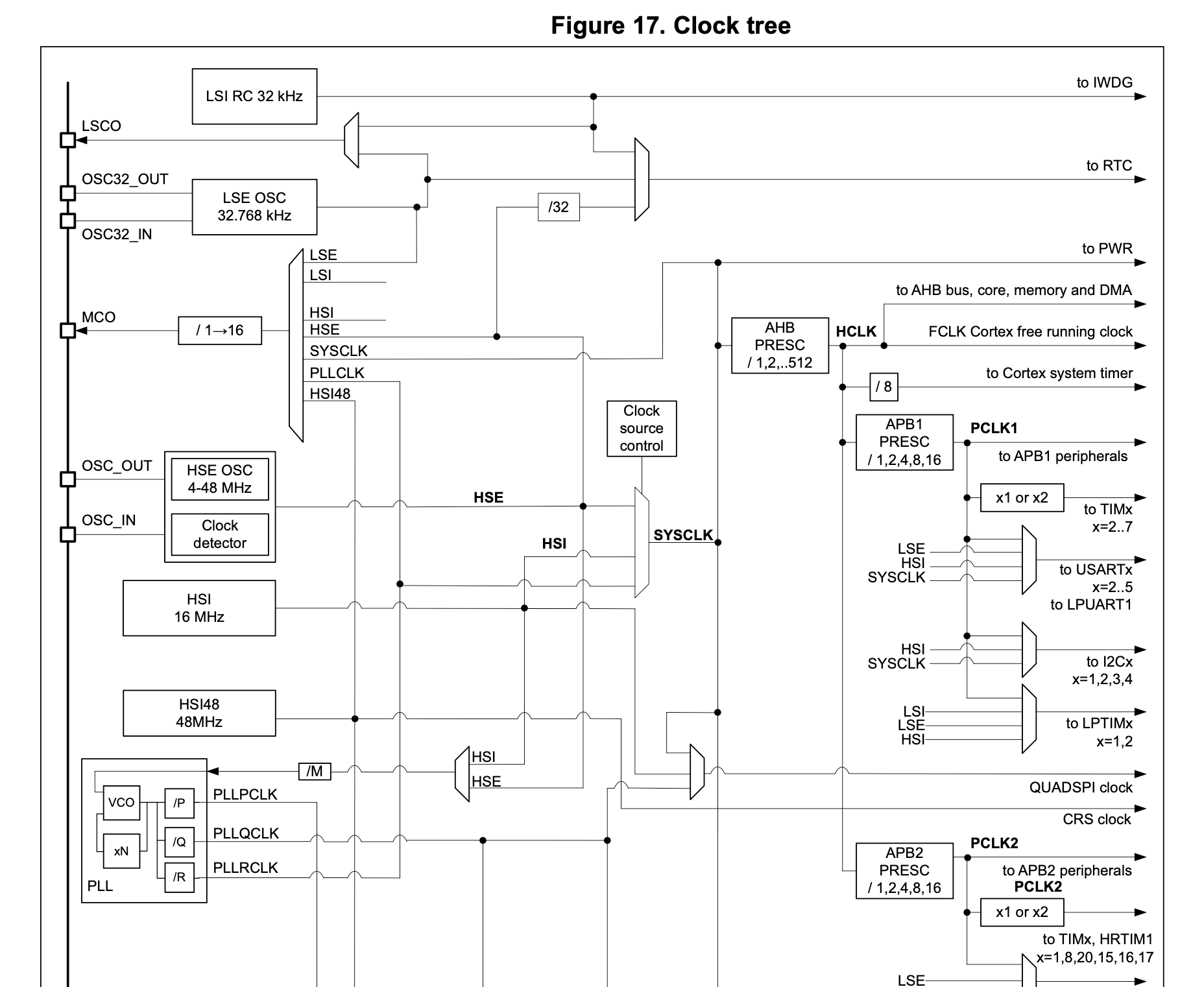
While the reset (default) clock configuration of a microcontroller may be sufficient in many contexts, one may wish to adjust the clocks to strike the appropriate balance between execution speed, power consumption, and ability to match specific external frequencies (to avoid aliasing, comply with some standard, etc.)
Rust HALs attempt to solve clock configurations at runtime, at the cost of program size and potential accuracy.
Pinfigurator can be used to model the clock relationships explicitly. These requirements
{:device/name "stm32f401ccu6"}

(def-real crystal-freq ;; crystal oscillator on our breakout board
  (= (MHz 25)))

(def-real system-freq ;; desired system frequency (maximum known from datasheet)
  (= (MHz 84)))

(assert [_ "apb low speed prescaler (apb1)" "divided by 2"]) ;;apb1 max freq is 42MHz
(def-real apb1-freq
  (= (/ system-freq 2)))

(assert [_ "apb high-speed prescaler (apb2)" "not divided"]) ;;apb2 max freq is 84MHz
(def-real apb2-freq
  (= system-freq))

(assert (<= 192 ["rcc" "plln"] 432))

(def-int pllp)
;; Translate field enumeration variant "integers" into actual integers
(assert (or (and (= pllp 2) ["rcc" "pllp" "2"])
            (and (= pllp 4) ["rcc" "pllp" "4"])
            (and (= pllp 6) ["rcc" "pllp" "6"])
            (and (= pllp 8) ["rcc" "pllp" "8"])))

(assert ["rcc" _ "HSE oscillator clock selected as PLL and PLLI2S clock entry"])

(def-real vco-clock
  ;; f(VCO clock) = f(PLL clock input) × (PLLN / PLLM)
  (= (* crystal-freq (/ ["rcc" "plln"]
                        ["rcc" "pllm"]))))

;; f(PLL general clock output) = f(VCO clock) / PLLP
(assert (= system-freq (/ vco-clock pllp)))

;; f(USB OTG FS, SDIO, RNG clock output) = f(VCO clock) / PLLQ
(assert (= (MHz 48) (/ vco-clock ["rcc" "pllq"])))
yield the following numeric constants (accessible at runtime, if needed by the application) and register configuration:
pub const CRYSTAL_FREQ: f32 = 25_000_000.;
pub const SYSTEM_FREQ : f32 = 84_000_000.;
pub const APB1_FREQ   : f32 = 42_000_000.;
pub const APB2_FREQ   : f32 = 84_000_000.;
pub const PLLP        : u32 = 4;
pub const VCO_CLOCK   : f32 = 336_000_000.;

pub fn init_registers() {
  unsafe {

    let rcc_cfgr = (0x40023800 + 0x8) as *mut u32;
    //                                                                     ppre1: HCLK divided by 2
    core::ptr::write_volatile(rcc_cfgr, 0b00__000__000__0__00__00000__000__100__00__0000__00__00);

    let rcc_pllcfgr = (0x40023800 + 0x4) as *mut u32;
    //                                             pllq: 2 <= u4 <= 15 = 7
    //                                                      pllsrc: HSE oscillator clock selected as PLL and PLLI2S clock entry
    //                                                               pllp: PLLP=4
    //                                                                      plln: 50 <= u9 <= 432 = 336
    //                                                                                 pllm: 2 <= u6 <= 63 = 25
    core::ptr::write_volatile(rcc_pllcfgr, 0b0010__0111__0__1__0000__01__0__101010000__011001);

  }
}
Note that the integer fields are annotated with bounds and selected value.
E.g., pllq: 2 <= u4 <= 15 = 7 means that field pllq is a 4-bit integer between 2 and 15 inclusive, and in this case was chosen to be 7.
Of course, standalone clock configuration is a well-solved problem for practitioners, even if only by copy/pasting popular configurations or relying on library defaults.
Pinfigurator’s approach shines when application-specific numeric relationships must be found. For example, when I made a spin coater with a brushless drone motor, I needed to communicate with its electronic speed controller via a 50 Hz PWM signal (20ms period) with pulses between 1–2ms.
Such a signal can be generated with a hardware timer peripheral, but it can be tricky to choose the relevant parameters:
- a timer’s frequency is determined by the system clock domain to which it’s attached, possibly divided by a prescaler
- timers are 16 or 32 bits
- an “auto-reload value” can be set so the timer restarts before it counts up to its full 16 or 32-bit range
- a timer has up to 4 channels, each of which has a “capture/comparison register” (CCR) value that is compared with the timer’s current count and generates an output (e.g., pin high when count below CCR, low when count equal to or greater than CCR)
For example, if we have a 16-bit timer on a 48 MHz clock domain, we can set its prescaler to 48, auto-reload to 1000, and channel 3’s CCR to 200, which will generate a square wave with 20% duty cycle and 1 kHz frequency (1 MHz / 1000). The output will be high for the first 200 timer ticks (200 / 1 MHz = 200 microseconds) then low for the next 800. In terms of “dynamic range”, the application can adjust the duty cycle in increments of 0.1% (by changing channel 3’s CCR value from 0–1000).
If that single toy example felt tedious, imagine trying to satisfy and optimize clocks, timers, and prescalers across multiple logically independent application functions.
Here’s what the Pinfigurator requirements looked like for my spin coater (incomplete listing, referencing some clock-related variables similar to the previous example):
(def-pin throttle
  (signal ch1))

(def-peripheral throttle-timer
  (peripheral throttle)
  ;;don't want this to be advanced control timer
  (not= tim1))

(def-real clock-bus-freq)

;; From page 84 of the reference manual RM0368:
;; The timer clock frequencies for STM32F401xB/C and STM32F401xD/E are automatically set by hardware. There are two cases:
;; 1. If the APB prescaler is 1, the timer clock frequencies are set to the same frequency as that of the APB domain to which the timers are connected.
;; 2. Otherwise, they are set to twice (×2) the frequency of the APB domain to which the timers are connected.
(assert (or (and (= throttle-timer #{tim1 tim9 tim10 tim11})
                 (= clock-bus-freq
                    (ite [_ "apb high-speed prescaler (apb2)" "not divided"]
                         apb2-freq
                         (* 2 apb2-freq))))
            (and (= throttle-timer #{tim2 tim3 tim4 tim5})
                 (= clock-bus-freq
                    (ite [_ "apb low speed prescaler (apb1)" "not divided"]
                         apb1-freq
                         (* 2 apb1-freq))))))

(def-real clock-freq
  (= (/ clock-bus-freq (+ 1 [throttle-timer "prescaler value"]))))

(def-real clock-tick
  (reciprocal clock-freq))

;; The "1" field matches channel 1, the signal we specified on the pin.
(assert [throttle-timer 1 "channel is active as long as TIMx_CNT<TIMx_CCRy"])

(assert (= 1 [throttle-timer "capture/compare 1 output enable"]))
(assert [throttle-timer "auto-reload preload" "enable"])

;; target waveform has 50 Hz frequency (20 ms period)
(assert (approx (* [throttle-timer "auto-reload value"] clock-tick)
                (ms 20)))

;; and high pulses be 1--2ms long (motor controller interprets 1ms = 0% speed, 2ms = 100% speed)
(def-real pulse-min-period
  (= (us 1000)))

(def-real pulse-max-period
  (= (us 2000)))

(def-int min-throttle
  ;;to_int rounds down: "the largest integer n that satisfies (<= (to_real n) r)"
  (= (+ 1 (to_int (/ pulse-min-period clock-tick)))))

(def-int max-throttle
  (= (to_int (/ pulse-max-period clock-tick))))

;;z3 doesn't do nonlinear optimization well, so just reduce to satisfiability by insisting we have a wide dynamic range
(assert (> (- max-throttle min-throttle) 3000))
with the application code using the generated constants with a runtime-provided desired throttle argument (floating-point zero to one):
let set_throttle = |s: &mut State, throttle: f32| {
    s.current_throttle = throttle;
    throttle_timer().ccr1.write(|w| {
        w.ccr().bits(
            MIN_THROTTLE as u16 + (throttle * (MAX_THROTTLE - MIN_THROTTLE) as f32) as u16,
        )
    });
};
A few notes on the requirements:
- The “unit” functions like
us,ms, etc. just scale numbers to seconds and are used for readability (though Frink-like dimensional modeling and consistency checking would be a neat addition!) - Because SMT-LIB is total, division by zero is “allowed” (a trap for new players!), which is why Pinfigurator includes a
reciprocalboolean predicate:
(define-fun reciprocal ((x Real) (y Real)) Bool
 (and (not (= 0 y))
      (= x (/ 1.0 y))))
Iterative synthesis
A neat SMT solver trick to find all possible solutions for a set of requirements is to, after you’ve found the first solution, add the requirement “but not this solution” and solve again (repeat as desired). This functionality is built-in to Pinfigurator and is useful for queries:
For example, which pins are on port C?
$ echo '{:device/name "stm32f401ccu6"} (def-pin foo (port c))' | pinfigurator --explore foo

  foo
  pc13
  pc14
  pc15
or which pins can be used for serial communication?
$ echo '
  {:device/name "stm32f401ccu6"}

  (def-pin tx-pin
    (signal tx))

  (def-pin rx-pin
    (signal rx))

  (def-peripheral periph
    (peripheral rx-pin)
    (peripheral tx-pin))
' | pinfigurator --explore tx-pin --explore rx-pin --explore periph

              tx-pin               rx-pin               periph
                 pa2                  pa3               usart2
                pa11                 pa12               usart6
                 pa9                 pa10               usart1
                 pb6                 pa10               usart1
                pa15                 pa10               usart1
                 pa9                  pb3               usart1
                pa15                  pb3               usart1
                 pb6                  pb3               usart1
                 pa9                  pb7               usart1
                 pb6                  pb7               usart1
                pa15                  pb7               usart1
Each row corresponds to a unique solution, so here we see that usart2 and usart6 only have a single pair of tx/rx pins each, whereas usart1 can map its tx and rx signals to 3 pins each, for 9 possible configurations.
Implementation
Pinfigurator is about 3000 lines of Clojure, compiled to a native binary via GraalVM and invoked via the command line.
Pinfigurator is implemented as series of “passes” which transform the input forms into an SMT-LIB specification. These passes:
- expand syntax (as described earlier)
- sort definitions (Unlike SMT-LIB, Pinfigurator allows use before declaration)
- introduce SMT-LIB variables to represent the values of registers and their fields, as well as user-facing integers and reals
- add the constraints one never specifies but always wants (variables should resolve to distinct pins/peripherals, pins assigned to variables have their GPIO ports enabled, peripherals assigned to variables should have their clocks enabled, etc.)
- expand register/field/value and register/field tuples into boolean and integer terms, respectively (including any string concatenation and property lookup function expansion)
- introduce the SMT-LIB variables referenced by these terms (one variable for each referenced register field)
After these passes, the SMT-LIB problem is then combined with a model of both the general microcontroller semantics (e.g., that every pin must be in one of Input, Output, Analog, or Alternate Function mode) as well as the specifics of the microcontroller in question (that it has tim1, tim2, tim3; alternate function af3 of pin pb7 maps it to tim3’s ch1, etc.).
(These SMT-LIB forms are trivial to generate via backtick.)
This (now very large) SMT-LIB specification is then solved by Z3 and the solution emitted as a standalone Rust file intended to be checked into and used by a standalone application project.
The underlying data — the microcontroller register definitions (addresses, names, descriptions, enumeration variants, etc.) — are parsed from manufacturer-provided SVD files (XML) and modm-devices, then stored in an in-memory DataScript database, which is baked into the Pinfigurator binary.
This database is used extensively by model generation and code emission stages.
For example, during model generation total functions like (declare-fun driver (Peripheral) Driver) are defined extensionally:
(assert
 (and ~@(for [[r d] (d/q '{:find [?r ?d]
                           :where [[?p-id :peripheral/name ?r]
                                   [?p-id :peripheral/driver ?d-id]
                                   [?d-id :driver/name ?d]]}
                         db)]
          (template
           (= (driver (as ~(munge r) Peripheral))
              (as ~(munge d) Driver))))))
which expands into something like
(assert
 (and (= (driver (as tim1 Peripheral)) (as tim Driver))
      (= (driver (as tim2 Peripheral)) (as tim Driver))
      (= (driver (as uart1 Peripheral)) (as uart Driver))
      (= (driver (as uart2 Peripheral)) (as uart Driver))
      ...))
(The type-casting as is used for disambiguation, since sometimes ST’s XML specifies singleton peripherals without a numeric suffix, e.g., usb might be the name of both the peripheral and the driver.)
After a solution is found, it’s added into this database to support emitting Pinfigurator’s commented code output. For example, the table of mapped pins:
// Mapped pins:
//
// led                       pc13  output
// x-a-in1                   pb4   tim3 ch1 (af2)
// x-a-in2                   pb5   tim3 ch2 (af2)
// x-b-in1                   pb0   tim3 ch3 (af2)
is generated by:
(when-let [pin-variables (->> solution
                              (d/q '{:find [?v] :where [[?v :variable/value ?p]
                                                        [?p :pin/name]]})
                              (map (fn [[eid]] (d/entity solution eid)))
                              (sort-by #(-> % :variable/name meta :line))
                              seq)]

  (println "// Mapped pins:")
  (println "//")
  (doseq [v pin-variables]
    (println (format "// %-25s %-5s %s"
               (str (:variable/name v))
               (:pin/name (:variable/value v))
               (match (:variable/value v)
                 {:pin/mode af-mode
                  :signal/_pins {:signal/name signal-name
                                 :peripheral/_signals {:peripheral/name peripheral-name}}}
                 (str peripheral-name " " signal-name " (" af-mode ")")

                 {:pin/mode mode}
                 mode)))))
Note the first match clause uses DataScript’s entity reverse-reference syntax (:signal/_pins and :peripheral/_signals) to “walk backwards” from pin to signal and from signal to peripheral to extract the names.
Honestly, DataScript is just a super handy graph database and I cannot recommend it highly enough =D
Design goals / experience notes
I first ran into the pin configuration problem in 2019 when I built a Vive Lighthouse receiver by mapping together the timers and comparators of an stm32g4 microcontroller. (This was also my first time using stm32 and embedded Rust.) For that and later toy projects (touchpad, keyboards), I relied on the “Kevin does a crossword puzzle” approach to finding valid configurations.
In June 2021, I wrote a program to merge a few microcontroller XML datasets (anything to pass the time in arrival quarantine…) and built a web-based microcontroller search tool, which calculated alternate function mappings for desired signal/peripheral mappings.
This felt like a satisfying proof of concept and basic design/search tool, but wasn’t something that I ended up actually using since it didn’t generate code or allow for user-provided constraints.
Various relational/logical language ideas kicked around my head through September, when I spent a week at Gradient Retreat and implemented the initial language/compiler and packaged it up as a command-line utility.
The primary objective was to be actually usable, by me, to support my various embedded projects.
My design goals were:
Lightweight feel: Mentally easy to “just pick up and use” — no required project directory setup, configuration files, etc. Should be easier and faster to use Pinfigurator than to look something up in a datasheet PDF.
Speed: Fast enough for interactive use, with no hesitation or friction about refining requirements for even “trivial” reasons (e.g., “this solution works, but how about we move everything to the left side of the breakout board so I don’t need to reposition my breadboard?”). Furthermore, the pin configuration system shouldn’t negatively impact other stages of firmware development (making projects more complex to setup, increasing compile times, etc.)
Expressiveness: Half of my motivation was to explore SMT solver capabilities anyway, so I wanted Pinfigurator to support whatever logical assertions I was capable of formulating. (As the only user, I wasn’t worried about familiarity/learnability beyond “will I be able to understand this in a week?”.)
The evaluation criterion was “Am I actually using this thing?”, to which I can happily report success.
The CLI design in particular has worked out well, as it makes it easy to check-in generated output to application-specific repositories. This means there is no per-application-compile performance overhead (as there would be with a Rust macro/type-system design) and also that consuming applications are isolated from Pinfigurator changes (since it’s easy to keep old standalone binary versions around) and — if the configuration doesn’t need to change — the applications don’t actually rely on Pinfigurator at all (i.e., I’ll be able to compile them in a decade without having to first compile Pinfigurator).
The performance is decent, with a “hello world” like (def some-timer (driver tim)) emitting code in about 700 ms and more complex requirements (like the spin coater’s clock and PWM signal configuration) taking 5–10s.
Rough benchmarking indicates that the bulk of the time tends to be in tuple lookups (matching and disambiguating [register field value] against names/descriptions) rather than in the SMT solver itself, so there’s still likely a fair bit of headroom with a smarter compiler.
As for expressiveness, Pinfigurator only interprets a handful of custom forms; the are “passed through” to the solver, making it easy for one to use any SMT-LIB or Z3 features create abstractions or logical constraints.
Hacks and shortcomings
While it meets my current (minimal, hobbyist) embedded configuration needs, Pinfigurator is far from a fully-baked tool. Some hacks and shortcomings, in no particular order:
There are no “higher-order” language constructs, so it’s impossible to express things like “I need 5 groups of 4 pins each, each satisfying these group-wise (rather than pin-wise) constraints”. Perhaps Clojure macros could be an OK stopgap until proper language syntax and semantics could be established. Copy-paste is the current best solution here.
Pinfigurator only considers a single configured state, taking one from “reset” to “operating”. While this certainly covers a wide range of applications, it’d be neat if Pinfigurator considered more complex state machines and associated constraints; assigning pins/peripherals with respect to their clock domains / power consumption, and generating optimal transitions (in terms of, e.g., registers updated) to move firmware between various low-power and operating modes.
There’s no import or reuse mechanism, so if you want to carry around, e.g., clock/bus requirements between projects…copy/paste.
The manufacturer-provided SVD files sometimes differ from the manufacturer-provided PDF documentation (there’s a thriving open-source ecosystem dedicated to patching them), which means Pinfigurator’s tuple search interface doesn’t work as well as I’d initially hoped. A web IDE or LSP-based autocomplete system would be nicer (at least, for the people who prefer squiggles-as-you-type over compiler errors).
If requirements are inconsistent (e.g.,
(assert (= 1 2))), Pinfigurator will tell you, but won’t help you debug by, e.g., reducing your requirements to the minimal impossible set (the “unsatisfiability core”). To avoid this, I interactively build up my requirements one-by-one so that if I hit an “unsat”, I know it’s related to the most recently added constraints.
The biggest semantic flaw is that Pinfigurator’s models aren’t bidirectional: Constraints on, e.g., the pin-mode function will influence the synthesized constants of the relevant GPIO registers, but not in the reverse direction.
To avoid inconsistencies, one must use Pinfigurator’s predicates like:
(define-fun pull-down ((p Pin)) Bool
  (and (= Input (pin-mode p))
       [(str "gpio" (port p) "-pupdr")
        (str "pupd" (idx p))
        "pull-down"]))
rather than constraining GPIO pull up/down, mode, or alternate function registers directly.
A universal bi-implication would resolve this:
(assert (forall (p Pin)
          (= (= Input (pin-mode p))
             [(str "gpio" (port p) "-pupdr")
              (str "pupd" (idx p))
              "pull-down"])))
but in practice this makes Pinfigurator unusably slow. I suspect because it forces the solver to check every microcontroller pin, rather than just pins needed to satisfy the requirements. (Though this is a wild guess on my part — I have no idea how SMT solvers do their magic.)
Elsewhere in the sacrificing logical consistency for performance department: How explicitly should Pinfigurator model memory?
While I first attempted to model registers as 32-bit bitvectors and map tuple constraints onto bitvector slices, this yielded solutions with unconstrained bits set arbitrarily. (SMT solvers, like magic lamps and small children, have a knack for giving you exactly what you asked for rather than what you actually wanted.)
What we really want is a solution for the given constraints that also minimizes the changes from the register reset values (defaults). This makes our problem not just one of satisfiability, but of optimization — while Z3 allows one to express such problems (it extends SMT-LIB with soft-asserts), the performance is substantially worse than satisfaction problems.
So rather than model registers explicitly as bitvectors, Pinfigurator formulates the SMT-LIB problem using dedicated integer variables for only the fields which are referenced by the user requirements. Once a solution is found, these individual field values are “mixed in” to their containing registers and emitted as synthesized 32-bit constants.
While this greatly reduces the search space and hence improves performance, it means Pinfigurator cannot express low-level constraints formulated in terms of memory addresses and bit values (which might be helpful for modeling DMA and bit-banding mechanisms).
Fin.
Pinfigurator was my first experience using SMT solvers for a non-toy problem, and I’m quite pleased with where it ended up — it actually works as designed and is the most convenient tool I have for configuring pin/peripherals/signals in my embedded projects!
The ease with which I could generate SMT-LIB with Clojure was extremely useful, as it allowed me to:
- immediately spin up an end-to-end development loop on the core problem (modeling and solving)
- easily inspect/debug the generated SMT-LIB model to be solved
If I’d only had Z3’s Python API, had to generate syntax like MiniZinc’s, or write my own parser frontend, I probably wouldn’t have reached the “escape velocity” of an incrementally improvable working system.
The project has also made more bullish on SMT solvers in general.
They can of course be used for solving soduku, superoptimization, synthesizing programs that play games, and analyzing software designs and distributed systems.
However the ergonomics of using SMT solvers are still fairly rough — my sense is that one must understand not just the solver’s conceptual model (e.g., predicate logic) but also a general-purpose programming language with bindings so that problem-relevant data can be loaded, formulated as a logical problem, etc. And, within a general-purpose language, working with logical constructs feels somewhat clunky (the impedance mismatch is similar to, e.g., adding remote procedure calls, object-relational mappings, asynchronous execution, etc. to an imperative programming language).
So while SMT solvers have made a huge impact in academic computer science and within specialized fields — including SMT-based languages like Rosette (SMT + Racket) and Formulog (SMT + Datalog) — they don’t yet seem to have substantial mindshare in broader programming communities as a tool that can be picked up easily.
I’m curious how solvers might cross that gap, as automata theory did through regular expressions, immutable data structures through Clojure, and array programming through NumPy.
How might a “general purpose” language or visual environment (i.e., spreadsheet) reify SMT concepts as first class features together with the I/O “table stakes” for real-world settings (e.g., graphical or command-line interface, CSV import, HTTP calls, C ABI) to support widespread adoption?
The bulk of the Pinfigurator’s internal machinery isn’t specific to microcontrollers at all, and I’m curious what sort of language would allow me to rewrite its 3000 lines of Clojure into 300 lines of domain logic.
Thanks
Thanks to Matt Keeter and Valentin Hartmann for feedback on this writeup, Gary Bernhardt and Jamie Brandon for feedback on Pinfigurator language design.